


mic preamplifier circuit based tlc251
#mic preamplifier
#TLC251
#low power
#battery operated
#audio signal
#low bias
#frequency response
#operational amplifier
#schematic diagram
#low-cost
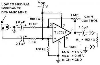
Description: The schematic diagram of a microphone preamplifier is based on the operational amplifier TC251. The TC251 operates with low bias and functions with a supply voltage of only 1.5 V, drawing an electric current of just 10 mA, making it suitable for battery operation. The circuit has a frequency response of 3dB, ranging from 27 Hz to 4.8 kHz. The TC251 is a low-cost, low-power programmable operational amplifier designed to work with single or dual power supplies. Its input common-mode range extends to the negative rail, and its low power consumption makes it ideal for battery-powered or energy-efficient applications. A bias-select pin allows programming of one of three AC performance and power-dissipation levels to accommodate various applications. The series operates down to a 1.4 V supply and remains stable at unity gain.
The microphone preamplifier circuit utilizing the TC251 operational amplifier is designed to enhance the signal from a microphone before it is processed by subsequent audio equipment. The TC251 is particularly advantageous in portable audio applications due to its low operating voltage and minimal current draw, which prolongs battery life.
The circuit's design includes a biasing network that ensures optimal performance across its specified frequency range, maintaining fidelity in sound reproduction. The frequency response of 27 Hz to 4.8 kHz is suitable for capturing the nuances of voice and instruments, making it effective for various audio applications, including recording and live sound reinforcement.
Incorporating a bias-select pin allows for flexibility in configuring the preamplifier to meet specific application requirements. By selecting different bias settings, the user can optimize the circuit for either lower power consumption or enhanced performance, depending on the needs of the application. This feature is particularly beneficial in scenarios where battery life is critical, allowing the designer to balance performance and efficiency.
The TC251's stability at unity gain ensures reliable operation in feedback configurations, which is essential for maintaining signal integrity in audio processing. Overall, the microphone preamplifier circuit based on the TC251 operational amplifier represents a robust solution for low-power, high-performance audio applications.Here the schematic diagram of mic preamplifier which build based on operational amplifier TC251. The TLC251 is operating in low bias. The circuit works with only 1. 5 V supply draws electric current of only 10 mA, so the battery operation will be prefered. Circuit frequency response is 3dB, 27 Hz to 4. 8 kHz. The TLC251 are low-cost, low-power progr ammable operational amplifiers designed to operate with single or dual power supplies. Because the input common-mode range extends to the negative rail and the power consumption is very low, this chip is ideally suited for battery-powered or energy-conserving applications. A bias-select pin can be used to program one of three ac performance and power-dissipation levels to suit the application.
The series features operation down to a 1. 4V supply and is stable at unity gain.
The microphone preamplifier circuit utilizing the TC251 operational amplifier is designed to enhance the signal from a microphone before it is processed by subsequent audio equipment. The TC251 is particularly advantageous in portable audio applications due to its low operating voltage and minimal current draw, which prolongs battery life.
The circuit's design includes a biasing network that ensures optimal performance across its specified frequency range, maintaining fidelity in sound reproduction. The frequency response of 27 Hz to 4.8 kHz is suitable for capturing the nuances of voice and instruments, making it effective for various audio applications, including recording and live sound reinforcement.
Incorporating a bias-select pin allows for flexibility in configuring the preamplifier to meet specific application requirements. By selecting different bias settings, the user can optimize the circuit for either lower power consumption or enhanced performance, depending on the needs of the application. This feature is particularly beneficial in scenarios where battery life is critical, allowing the designer to balance performance and efficiency.
The TC251's stability at unity gain ensures reliable operation in feedback configurations, which is essential for maintaining signal integrity in audio processing. Overall, the microphone preamplifier circuit based on the TC251 operational amplifier represents a robust solution for low-power, high-performance audio applications.Here the schematic diagram of mic preamplifier which build based on operational amplifier TC251. The TLC251 is operating in low bias. The circuit works with only 1. 5 V supply draws electric current of only 10 mA, so the battery operation will be prefered. Circuit frequency response is 3dB, 27 Hz to 4. 8 kHz. The TLC251 are low-cost, low-power progr ammable operational amplifiers designed to operate with single or dual power supplies. Because the input common-mode range extends to the negative rail and the power consumption is very low, this chip is ideally suited for battery-powered or energy-conserving applications. A bias-select pin can be used to program one of three ac performance and power-dissipation levels to suit the application.
The series features operation down to a 1. 4V supply and is stable at unity gain.
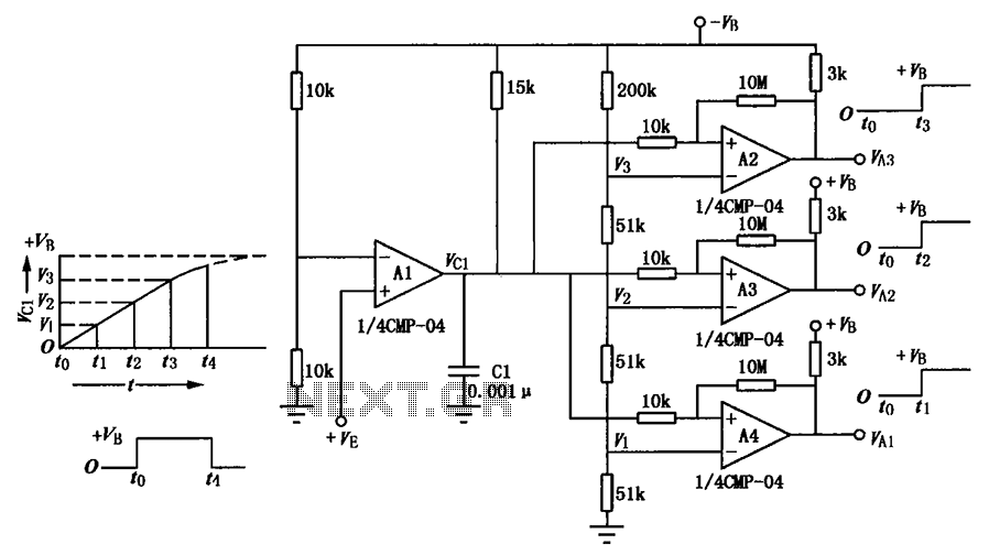
Delay circuit of a multi-level output
A multi-stage delay circuit is presented in this schematic. The operational amplifiers are configured as comparators. Operational amplifier A1 operates when the voltage at the inverting input exceeds + VE. As the voltage at the inverting input of operational amplifiers...
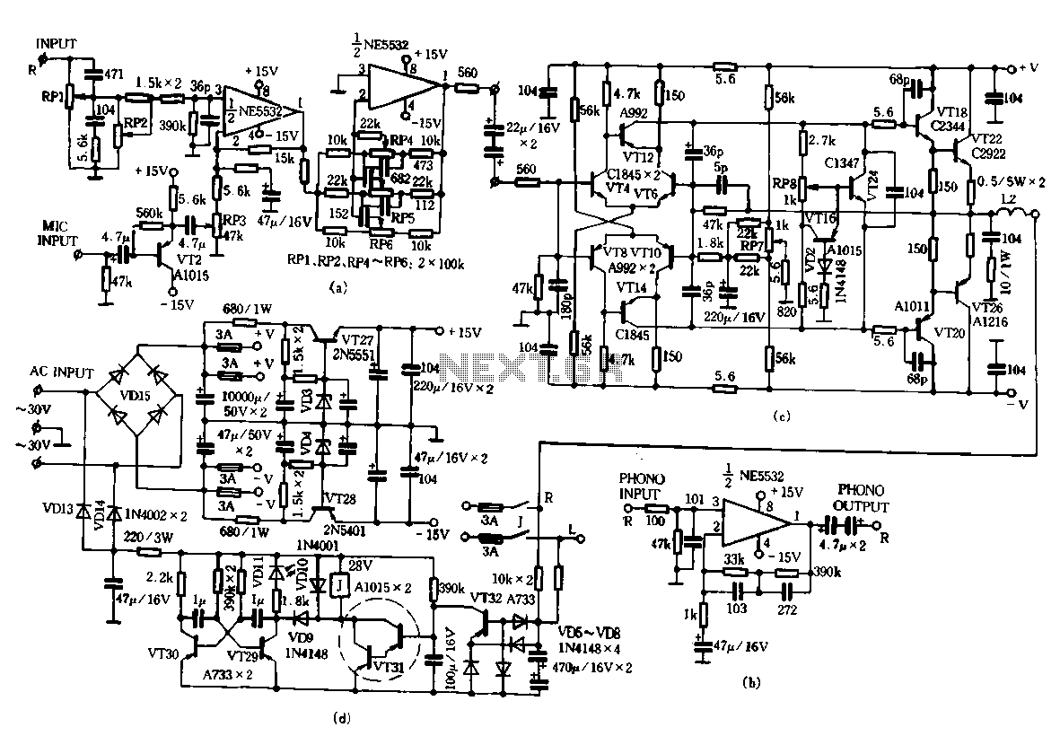
TA-1500 fever amplifier circuit
Only the R channel is shown, with the original reference PCB label. Figure (a) illustrates the front tone circuit, which consists of a common negative feedback operational amplifier in an RC circuit configuration. The microphone signal is amplified by VTz,...
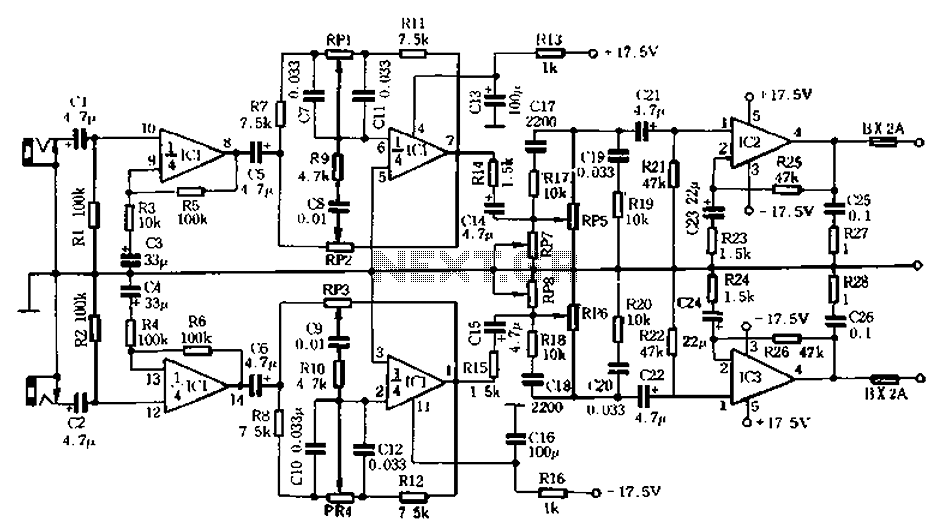
Homemade whole integrated circuit amplifiers 01
The circuit depicted in Figure 5-60 and Figure 6 utilizes an operational amplifier (op-amp) configured as a channel pre-amplifier to address the signal loss introduced by the tone control circuit. Additionally, another group of op-amps forms a channel-driven stage amplifier...
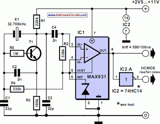
Very Low Power 32kHz Oscillator
The 32-kHz low-power clock oscillator provides several advantages compared to traditional oscillator circuits that utilize a CMOS inverter. These inverter circuits often exhibit issues such as significant fluctuations in supply currents across a 3V to 6V supply range, making it...
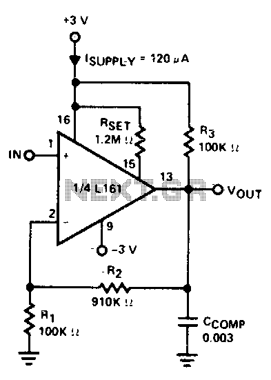
X10 operational amplifier
The amplifier is 3 dB down at 100 kHz and has a slew rate of 0.02 V/µs.
The amplifier's performance characteristics indicate that it experiences a 3 dB attenuation at a frequency of 100 kHz. This specification suggests that at this...
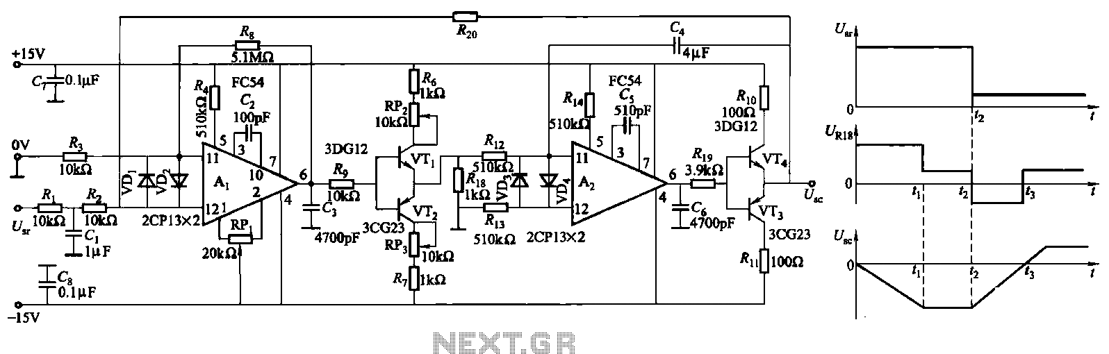
ZKJ-S-type buffer controller circuit
The ZKJ-S-type buffer controller circuit is designed for motor starting slip control. This buffer controller is composed of two operational amplifiers, Ai and Az. The operational amplifier Ai functions as a speed amplifier that saturates, while Az acts as an...
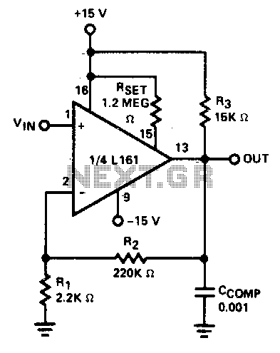
X100 operational amplifier
The amplifier has a gain-bandwidth product of 20 MHz, with a slew rate of 0.3 V/µs.
The amplifier's gain-bandwidth product (GBP) of 20 MHz indicates that the product of the amplifier's gain and the bandwidth at which that gain is applicable...
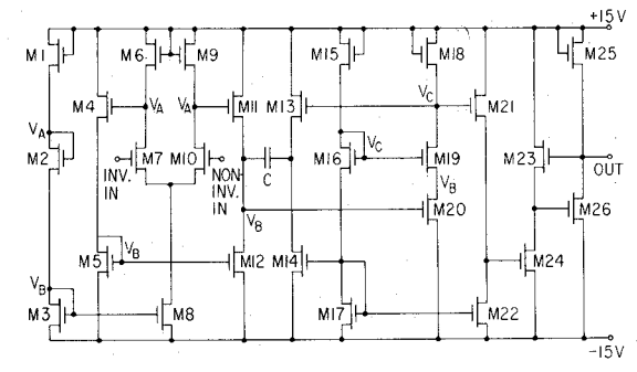
cut the feed forward in the miller compensation with voltage buffer
An internally compensated operational amplifier has been fabricated using n-channel Al-gate MOS technology, utilizing only enhancement mode devices. The circuit is designed to ensure that its performance remains insensitive to process parameters. The input stage consists of a source-coupled differential...
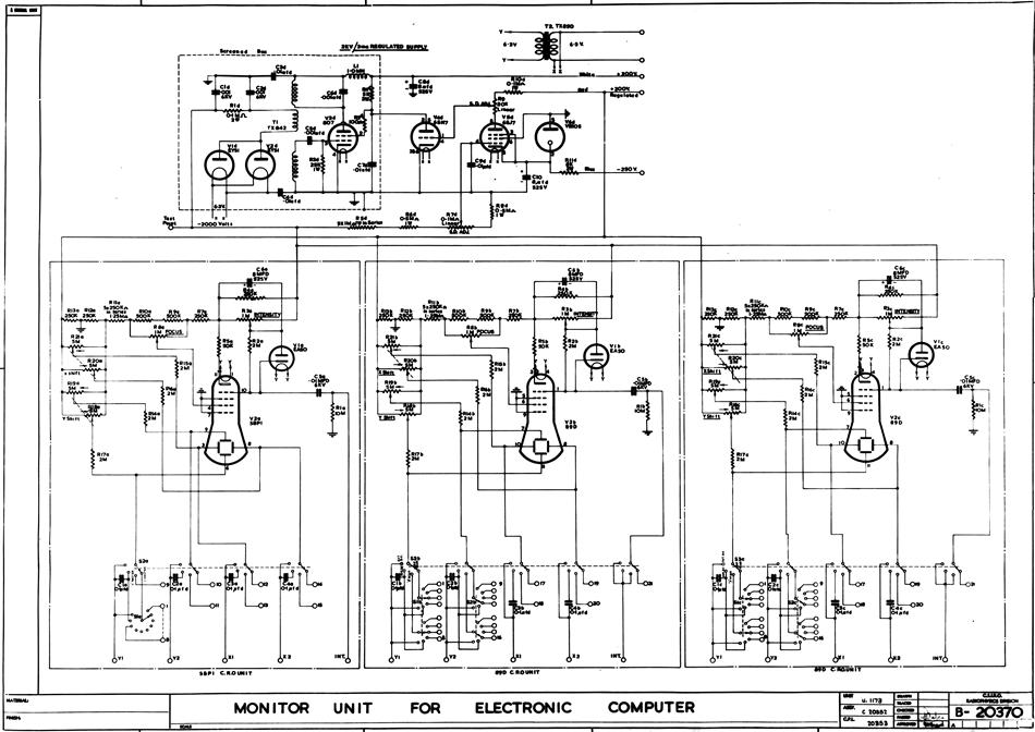
schematic monitor
A schematic diagram in hard copy related to the computer CSIRAC, possibly dated 1961. This schematic diagram illustrates the detailed connections between all the components in the circuit. Such diagrams were utilized for circuit construction and subsequent testing. For CSIRAC,...