


Notch filter circuit diagram MC33171
#MC33171
#notch filter
#op amp
#bandwidth
#high conversion rate
#trap circuit
#signal processing
#filter design
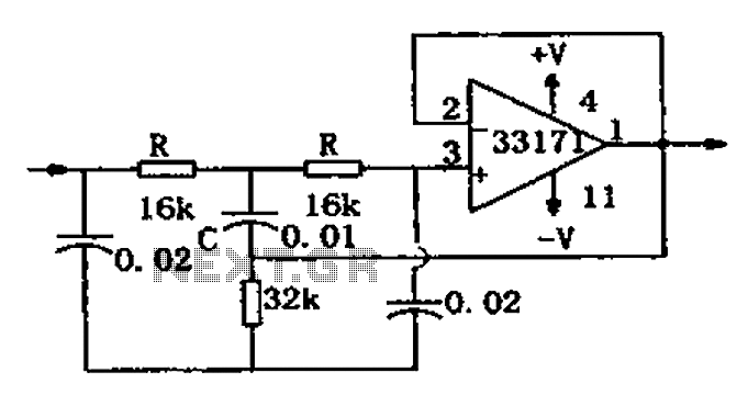
Description: The trap circuit utilizes a high-performance operational amplifier, MC33171, to create the trap. This device features a wide bandwidth and high conversion rate. The component values can be modified by adjusting the capacitance of capacitor C and the resistance of two resistors R, allowing for changes in the notch frequency, expressed as f = 1/(4RC).
The trap circuit is designed to selectively filter out specific frequencies from a signal while allowing other frequencies to pass through. The MC33171 operational amplifier serves as the core component due to its excellent performance characteristics, including a high slew rate and low noise, which are essential for maintaining signal integrity in high-frequency applications.
In this circuit, the notch frequency can be adjusted by varying the values of the capacitor C and the resistors R. The formula for the notch frequency, f = 1/(4RC), indicates that the frequency response of the circuit is inversely proportional to the product of the resistance and capacitance values. Therefore, increasing the capacitance or resistance will lower the notch frequency, while decreasing these values will raise it.
The design typically consists of a feedback loop that incorporates the operational amplifier, capacitor, and resistors. The configuration ensures that the desired frequency is attenuated while minimizing the impact on adjacent frequencies. The high-performance characteristics of the MC33171 allow for precise tuning and effective filtering, making this trap circuit suitable for applications in audio processing, communication systems, and signal conditioning.
Overall, this trap circuit exemplifies the application of operational amplifiers in electronic filtering, demonstrating how component selection and configuration can be leveraged to achieve specific signal processing goals. As shown for the trap circuit. The circuit uses a high-performance op amp device MC33171 constitute trap. The device has a wide band and a high conversion rate. In the illustra ted component values by changing the value of a capacitor C and two resistors R, and other available notch frequency, its value is: f 1/4 RC.
The trap circuit is designed to selectively filter out specific frequencies from a signal while allowing other frequencies to pass through. The MC33171 operational amplifier serves as the core component due to its excellent performance characteristics, including a high slew rate and low noise, which are essential for maintaining signal integrity in high-frequency applications.
In this circuit, the notch frequency can be adjusted by varying the values of the capacitor C and the resistors R. The formula for the notch frequency, f = 1/(4RC), indicates that the frequency response of the circuit is inversely proportional to the product of the resistance and capacitance values. Therefore, increasing the capacitance or resistance will lower the notch frequency, while decreasing these values will raise it.
The design typically consists of a feedback loop that incorporates the operational amplifier, capacitor, and resistors. The configuration ensures that the desired frequency is attenuated while minimizing the impact on adjacent frequencies. The high-performance characteristics of the MC33171 allow for precise tuning and effective filtering, making this trap circuit suitable for applications in audio processing, communication systems, and signal conditioning.
Overall, this trap circuit exemplifies the application of operational amplifiers in electronic filtering, demonstrating how component selection and configuration can be leveraged to achieve specific signal processing goals. As shown for the trap circuit. The circuit uses a high-performance op amp device MC33171 constitute trap. The device has a wide band and a high conversion rate. In the illustra ted component values by changing the value of a capacitor C and two resistors R, and other available notch frequency, its value is: f 1/4 RC.

Notch filter uses an operational amplifier
This notch filter is beneficial for tunable band-reject applications in the audio range. The specified values will provide a tuning range of approximately 300 to 1500 Hz.
The notch filter is designed to attenuate a specific frequency while allowing others to...
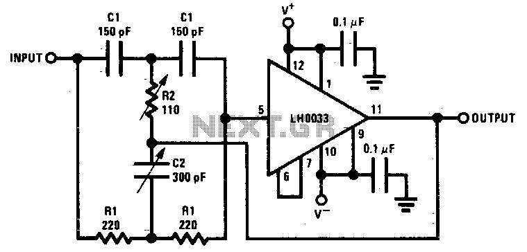
4.5Mhz notch filter
Component value sensitivity is extremely critical, as are temperature coefficients and matching of the components. Best performance is attained when perfectly matched components are used and when the gain of the amplifier is unity. To illustrate, the quality factor Q...
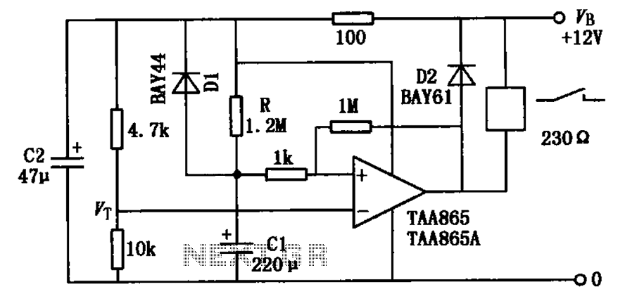
Op amp circuit diagram relay delay release
The circuit illustrated in the figure is a delayed release operational amplifier relay circuit. When the power switch is activated, a resistor of 4.7k is connected to the inverting input terminal of the operational amplifier. Additionally, a 10k resistor is...
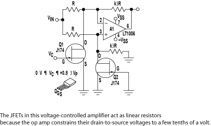
Op Amp And Two JFETs Form A Voltage-Controlled Amplifier
A simple linear voltage-controlled amplifier can be constructed with one operational amplifier (op amp) and two junction field-effect transistors (JFETs). This amplifier can achieve an 80-dB dynamic control range with less than ±0.2% linearity error for 0 V.
The described circuit...
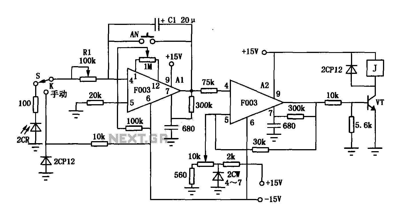
Op amp F003 composition of automatic exposure timer circuit
The F003 circuit is a versatile photographic component that functions as an operational amplifier amplifying automatic timer circuit. The operational amplifier A1 serves as an integrator, while operational amplifier A2 is configured as a comparator. A 2CR silicon photocell generates...
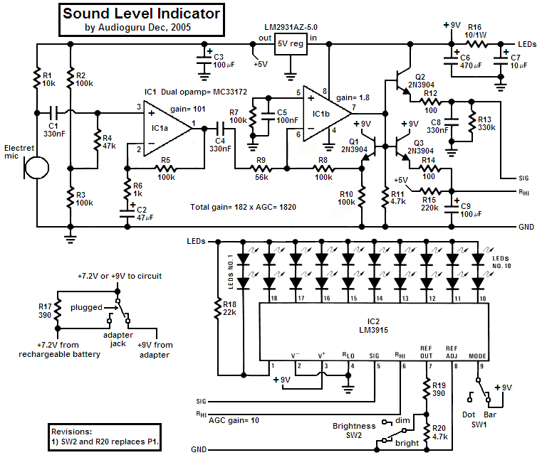
Audio and amplifier circuits
This high-Q notch filter operates at 60 Hz and is based on the "Twin-T" design. It creates a significant notch in the response curve at approximately 59.7 Hz, effectively eliminating 60 Hz hum and noise from audio recordings or live...
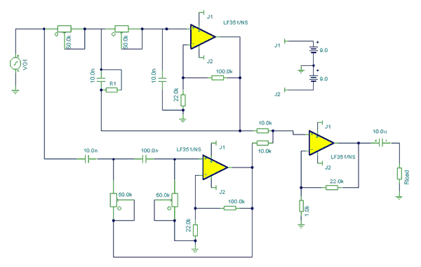
audio notch filter
At first glance, this circuit appears to be quite complex; however, when analyzed, it can be segmented into high-pass and low-pass filter sections, which are subsequently connected to a summing amplifier with a gain of approximately 20 times. The supply...
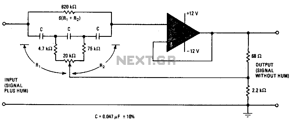
Tunable notch filter to suppress hum
This narrow stop-band filter can be adjusted using a potentiometer to position the notch frequency anywhere from 45 to 90 Hz. It effectively attenuates power-line hum and other unwanted signals by at least 30 dB. The circuit is cost-effective to...
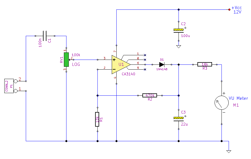
Peak Reading Audio Level Meter
This simple circuit, designed with a minimal component count, indicates peak audio response on an analog meter, similar to a tape recorder's meter. It employs an operational amplifier configured as a non-inverting amplifier, with the addition of a diode in...