


op amp Trouble transferring schematic (working) to actual circuit (not working)
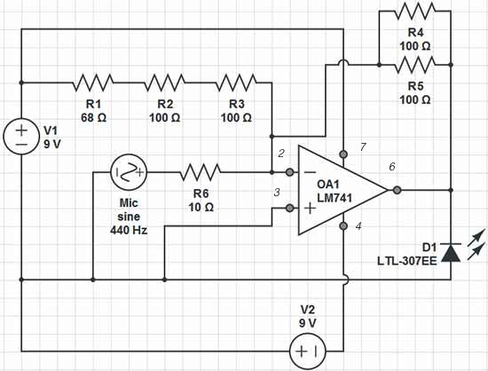
Description: Red = V+, Black = V-, Green = GND, Yellow = Mic Input, Orange = LED Output. The op-amp used is an LM741, which is intended to adjust the peak brightness of the LED based on the ambient sound level. Although the simulator functions correctly, the physical circuit exhibits a discrepancy where the op-amp fails to maintain equal input voltages (4.4 V difference). Additionally, the voltage drop across the resistors is also incorrect. It is suspected that this issue may stem from the microphone's high impedance, causing the op-amp to apply 1.7V across the LED, which could vary depending on the LED type. If the microphone has a near-zero DC resistance (as in a moving coil type), the output voltage will be approximately zero. Conversely, a higher DC resistance from the microphone will influence the DC output setpoint.
The circuit involves an LM741 operational amplifier configured to modulate the brightness of an LED based on sound input from a microphone. The microphone, designated as the Yellow input, serves as a transducer that converts sound waves into an electrical signal. The output of the microphone is fed into the non-inverting input of the op-amp, while the inverting input is connected to a reference voltage, likely derived from a voltage divider or a fixed reference.
The power supply connections are clearly defined, with Red representing the positive voltage (V+), Black for the negative voltage (V-), and Green for the ground (GND). The op-amp's output, which drives the LED (Orange output), should theoretically vary in response to the sound level detected by the microphone. However, the circuit's performance is hindered by the high impedance of the microphone, which can lead to significant voltage drops and incorrect biasing conditions for the op-amp.
To ensure proper functionality, it is crucial to consider the input impedance of the op-amp relative to the microphone's output. If the microphone's DC resistance is too high, it will prevent the op-amp from achieving the necessary voltage levels to drive the LED effectively. This misalignment can lead to an output voltage that does not correspond accurately to the ambient sound levels, resulting in the observed malfunction.
In practical applications, it is advisable to use a buffer stage between the microphone and the op-amp to mitigate impedance issues. A buffer can provide the necessary current drive while isolating the microphone from the load presented by the op-amp. Furthermore, careful selection of resistors in the feedback loop of the op-amp will help to set the gain appropriately, ensuring that the output voltage accurately reflects the sound levels and allows for proper LED brightness modulation.
In conclusion, addressing the impedance mismatch and ensuring proper voltage levels throughout the circuit will enhance the performance of the sound-activated LED system.Red = V+, Black = V-, Green = GND, Yellow = Mic Input, Orange = LED Output. The op-amp I`m using is an LM741. It`s supposed to change the peak brightness of the LED depending on the ambient sound level. The frustrating thing is that the simulator is happy with it, but on the board, the op-amp can`t even keep its inputs at the same voltage (4. 4 V difference). The voltage drop on the resistors is wrong too, and I think that`s caused by the former. do you have the schematic of the Falstad cct. Asking people to look over odd nodal netlists is akin to asking them to eat glass for you. ;) placeholder Apr 23 `13 at 0:31 A fatally fatally fatal problem is that IF the microphone is high impedance then the opamp is trying to place 1. 7V across the LED. What this does depends on the LED type. If the microphone has a DC resistance of close to zero (moving coil) then Vout will be close to zero.
Above that the mic DC resistance will affect the DCout setpoint.
The circuit involves an LM741 operational amplifier configured to modulate the brightness of an LED based on sound input from a microphone. The microphone, designated as the Yellow input, serves as a transducer that converts sound waves into an electrical signal. The output of the microphone is fed into the non-inverting input of the op-amp, while the inverting input is connected to a reference voltage, likely derived from a voltage divider or a fixed reference.
The power supply connections are clearly defined, with Red representing the positive voltage (V+), Black for the negative voltage (V-), and Green for the ground (GND). The op-amp's output, which drives the LED (Orange output), should theoretically vary in response to the sound level detected by the microphone. However, the circuit's performance is hindered by the high impedance of the microphone, which can lead to significant voltage drops and incorrect biasing conditions for the op-amp.
To ensure proper functionality, it is crucial to consider the input impedance of the op-amp relative to the microphone's output. If the microphone's DC resistance is too high, it will prevent the op-amp from achieving the necessary voltage levels to drive the LED effectively. This misalignment can lead to an output voltage that does not correspond accurately to the ambient sound levels, resulting in the observed malfunction.
In practical applications, it is advisable to use a buffer stage between the microphone and the op-amp to mitigate impedance issues. A buffer can provide the necessary current drive while isolating the microphone from the load presented by the op-amp. Furthermore, careful selection of resistors in the feedback loop of the op-amp will help to set the gain appropriately, ensuring that the output voltage accurately reflects the sound levels and allows for proper LED brightness modulation.
In conclusion, addressing the impedance mismatch and ensuring proper voltage levels throughout the circuit will enhance the performance of the sound-activated LED system.Red = V+, Black = V-, Green = GND, Yellow = Mic Input, Orange = LED Output. The op-amp I`m using is an LM741. It`s supposed to change the peak brightness of the LED depending on the ambient sound level. The frustrating thing is that the simulator is happy with it, but on the board, the op-amp can`t even keep its inputs at the same voltage (4. 4 V difference). The voltage drop on the resistors is wrong too, and I think that`s caused by the former. do you have the schematic of the Falstad cct. Asking people to look over odd nodal netlists is akin to asking them to eat glass for you. ;) placeholder Apr 23 `13 at 0:31 A fatally fatally fatal problem is that IF the microphone is high impedance then the opamp is trying to place 1. 7V across the LED. What this does depends on the LED type. If the microphone has a DC resistance of close to zero (moving coil) then Vout will be close to zero.
Above that the mic DC resistance will affect the DCout setpoint.
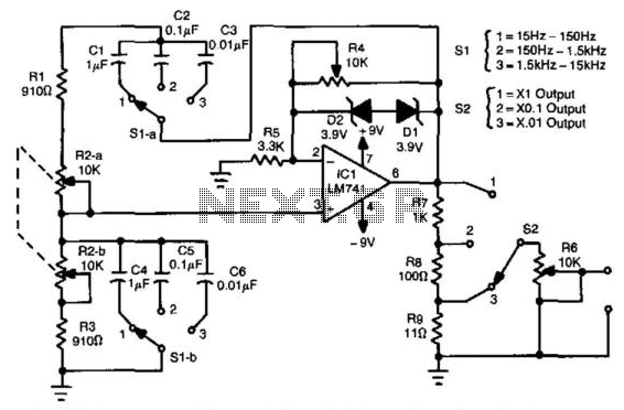
Three-Decade 15Hz To 15Khz Wien-Bridge Oscillator
In this circuit, an LM741 operational amplifier drives a Wien-bridge network utilizing two zener diodes as an amplitude limiter. Range selection is performed by a switch that selects between capacitors (C1 through C6), while tuning is achieved using a ganged...
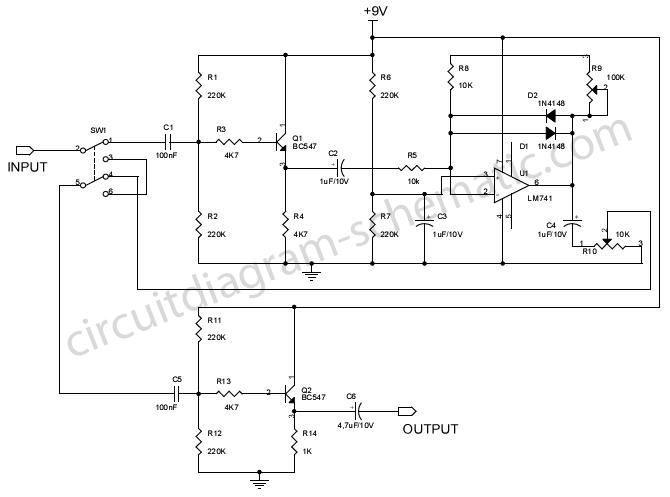
Fuzzbox Using LM741
Various tools can be utilized with a musical instrument to generate different sound effects, with the simplest being the repetition of tone, often referred to as echo. This equipment enhances the music being played. The circuit diagram is designed for...
LM741 Light Dark Sensor
A light/dark sensing circuit is highly useful and versatile for various renewable energy projects, including automatic lighting and security systems. The article on Light Dependent Resistors (LDR) explains how an LDR can be employed in simple circuits to control devices...
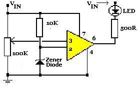
LM741 OpAmp Voltage Indicator
A simple voltage status monitor built around the LM741 operational amplifier. These circuits are recognized for their accuracy, ease of operation, and cost-effectiveness. The LM741 serves as an operational amplifier, widely used for various applications. The primary function of this...
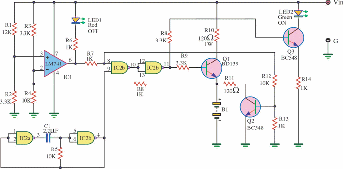
Dry Cell Battery Charger Using LM741
This is a dry cell battery charger circuit designed to charge batteries over a period of approximately 12 hours. When powered by a 9-volt supply, the circuit is configured to accommodate AA-sized batteries. If C or D-sized batteries are used,...
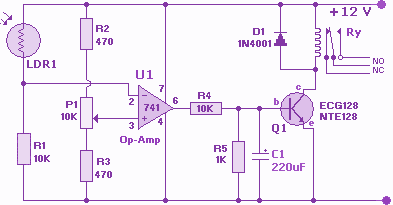
LM741 IC for Light Dark Sensor Circuit
The circuit below illustrates the use of the LM741 integrated circuit (IC) in a light and dark sensor configuration. This circuit offers several features, including a 1 Watt LED spotlight, making it suitable for a wide range of renewable energy...
LM741 OpAmp Voltage Indicator
A simple voltage status monitor built around the LM741 operational amplifier. These circuits are recognized for their accuracy, ease of operation, and cost-effectiveness. The LM741 serves as an operational amplifier, widely used for various applications. The primary function of this...
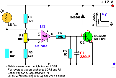
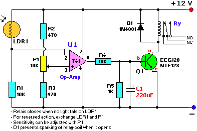
Light Dark Sensor With Relay Circuit Using LM741
The provided schematic diagram illustrates an LM741 light/dark sensor circuit, derived from the 741 Op-Amp Tutorial by Tony van Roon. The ECG128/NTE128 transistor can be replaced with any NPN transistor that meets the necessary gain and current specifications for the...
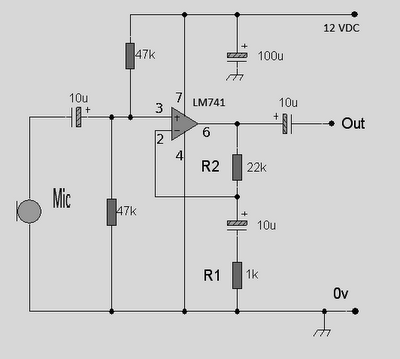
op amp lm741 pre amp mic schematic
This circuit is an Op-Amp Microphone Preamplifier that operates using a single power supply. It is suitable for both dynamic and electret microphones. The schematic illustrates the configuration with a dynamic microphone; however, for electret microphones, a pair of appropriate...