


Oscillation issue on THS4271
#THS4271
#oscillation
#differential input
#sine wave
#THS3091
#frequency
#amplifier
#signal generator
#feedback
#stability
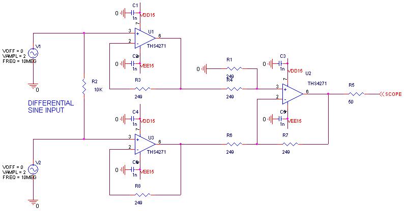
Description: An oscillation issue has been observed with the THS4271 operational amplifier. The circuit schematic is attached. A differential sine wave is applied to the positive and negative terminals, using a 10k differential resistor. The output oscillates at 300 MHz or at a mixed frequency, as indicated in the attachment. When the sine wave signal generator is turned off, the output continues to oscillate. Switching to a THS3091 with the recommended feedback resistor results in a clean output without oscillation. Questions have been raised regarding the supply voltage, as the schematic suggests a +/-15V (30V total) supply, while the THS4271 is only rated for a maximum of 16.5V total supply, indicating a potential over-voltage issue. Testing with reduced supply voltages of +/-5V or +/-7.5V is recommended to check for continued oscillation. Additional troubleshooting steps include isolating oscillation by examining the outputs of U1 and U3, ensuring all planes and fills are cut out below the input/output pins, and possibly cutting the trace from the U3 output to R6 to eliminate parasitic capacitance effects. Although the ground plane beneath the signal between the inverting and output nodes has been removed, concerns exist about cutting power planes. Probing the output through a 50-ohm resistance did not yield results, but increasing R3 and R8 from 249k to 499k seems to have resolved the oscillation issue.
The THS4271 is a high-speed operational amplifier designed for a variety of applications requiring fast response times and low distortion. However, it is crucial to adhere to the specified supply voltage limits to prevent device failure or unintended behavior such as oscillation. The differential input configuration with a 10k resistor indicates that the circuit is designed for high-frequency signal processing. The observed oscillation at 300 MHz suggests that the feedback network may be improperly designed or that the operational amplifier is being pushed beyond its rated specifications.
When troubleshooting the oscillation, it is essential to verify that the power supply voltages do not exceed the maximum ratings. Testing with lower voltages can help determine if the oscillation is related to supply issues or if it is a result of other circuit components. Inspecting the outputs of U1 and U3 for oscillation can provide insights into where the feedback loop may be causing instability.
In high-frequency applications, parasitic capacitance can significantly impact performance. Cutting traces or modifying the layout to minimize capacitance can help stabilize the circuit. The recommendation to isolate U3 by cutting the trace to R6 is a practical approach to eliminate feedback paths that could contribute to oscillation.
It is also important to ensure that all layers of the PCB are appropriately designed, with ground planes and signal traces laid out to minimize interference. Removing copper beneath input/output pins is a common practice to prevent unintended coupling and oscillation.
The increase in resistor values from 249k to 499k for R3 and R8 indicates an adjustment in the feedback network that has successfully mitigated the oscillation issue. This change likely affects the gain and bandwidth of the amplifier, and it is advisable to evaluate the performance of the circuit after these modifications to ensure that it meets the desired specifications without introducing other issues.
Overall, careful attention to component specifications, layout design, and feedback network adjustments is crucial for achieving stable performance in high-speed operational amplifier circuits.I got oscillation issueon THS4271. The circuit schematic is as attached. The input is differential sine wave on positive and negative terminals with 10k differential resistor. The output oscillates at 300Mhz or mixed frequency as attached. Once turn off the sine wave SG, the output continue to oscillate. If changing THS3091 with appropriate recomme nded Rf, the circuit is clean without oscillation. Could someone tell me what`s going on with THS4271 Are you using +/-15V (30V total) supplies as your schematic appears to indicate The THS4271 is only rated for up to 16. 5V total supply, so you are exceeding this limit. Does the circuit oscillate if you reduce the supplies to +/-5V or +/-7. 5V If the circuit still oscillates, try isolating the oscillation. Check if the outputs of U1 and U3 show an oscillation. Do you have all planes/fills cut out below the input/output pins, or just the layer immediately below the top layer The best practice is to remove all copper on all layers below the input/output pins Would it be possible to cut the trace from the U3 output to R6 to isolate U3 completely Perhaps the parasitic capacitance of the trace to R6 is causing U3 to oscillate.
I suggest cutting the top trace as I`ve shown in the image below. Cut and remove the trace to form a space for a resistor to be soldered across points 1 and 2 (red boxes). Thanks for the response! I did remove the ground plane under the signal between inverting and output node but not for power and other planes.
I am afraid there`s some other issues when I cut off the power planes. I also follow your instruction to probe output through 50 ohm resistance but it doesn`t work. I increase R3 and R8 FROM 249Kto 499K. It seems OK w/o oscillation. All content and materials on this site are provided "as is". TI and its respective suppliers and providers of content make no representations about the suitability of these materials for any purpose and disclaim all warranties and conditions with regard to these materials, including but not limited to all implied warranties and conditions of merchantability, fitness for a particular purpose, title and non-infringement of any third party intellectual property right. TI and its respective suppliers and providers of content make no representations about the suitability of these materials for any purpose and disclaim all warranties and conditions with respect to these materials.
No license, either express or implied, by estoppel or otherwise, is granted by TI. Use of the information on this site may require a license from a third party, or a license from TI. Content on this site may contain or be subject to specific guidelines or limitations on use. All postings and use of the content on this site are subject to the Terms of Use of the site; third parties using this content agree to abide by any limitations or guidelines and to comply with the Terms of Use of this site. TI, its suppliers and providers of content reserve the right to make corrections, deletions, modifications, enhancements, improvements and other changes to the content and materials, its products, programs and services at any time or to move or discontinue any content, products, programs, or services without notice.
The THS4271 is a high-speed operational amplifier designed for a variety of applications requiring fast response times and low distortion. However, it is crucial to adhere to the specified supply voltage limits to prevent device failure or unintended behavior such as oscillation. The differential input configuration with a 10k resistor indicates that the circuit is designed for high-frequency signal processing. The observed oscillation at 300 MHz suggests that the feedback network may be improperly designed or that the operational amplifier is being pushed beyond its rated specifications.
When troubleshooting the oscillation, it is essential to verify that the power supply voltages do not exceed the maximum ratings. Testing with lower voltages can help determine if the oscillation is related to supply issues or if it is a result of other circuit components. Inspecting the outputs of U1 and U3 for oscillation can provide insights into where the feedback loop may be causing instability.
In high-frequency applications, parasitic capacitance can significantly impact performance. Cutting traces or modifying the layout to minimize capacitance can help stabilize the circuit. The recommendation to isolate U3 by cutting the trace to R6 is a practical approach to eliminate feedback paths that could contribute to oscillation.
It is also important to ensure that all layers of the PCB are appropriately designed, with ground planes and signal traces laid out to minimize interference. Removing copper beneath input/output pins is a common practice to prevent unintended coupling and oscillation.
The increase in resistor values from 249k to 499k for R3 and R8 indicates an adjustment in the feedback network that has successfully mitigated the oscillation issue. This change likely affects the gain and bandwidth of the amplifier, and it is advisable to evaluate the performance of the circuit after these modifications to ensure that it meets the desired specifications without introducing other issues.
Overall, careful attention to component specifications, layout design, and feedback network adjustments is crucial for achieving stable performance in high-speed operational amplifier circuits.I got oscillation issueon THS4271. The circuit schematic is as attached. The input is differential sine wave on positive and negative terminals with 10k differential resistor. The output oscillates at 300Mhz or mixed frequency as attached. Once turn off the sine wave SG, the output continue to oscillate. If changing THS3091 with appropriate recomme nded Rf, the circuit is clean without oscillation. Could someone tell me what`s going on with THS4271 Are you using +/-15V (30V total) supplies as your schematic appears to indicate The THS4271 is only rated for up to 16. 5V total supply, so you are exceeding this limit. Does the circuit oscillate if you reduce the supplies to +/-5V or +/-7. 5V If the circuit still oscillates, try isolating the oscillation. Check if the outputs of U1 and U3 show an oscillation. Do you have all planes/fills cut out below the input/output pins, or just the layer immediately below the top layer The best practice is to remove all copper on all layers below the input/output pins Would it be possible to cut the trace from the U3 output to R6 to isolate U3 completely Perhaps the parasitic capacitance of the trace to R6 is causing U3 to oscillate.
I suggest cutting the top trace as I`ve shown in the image below. Cut and remove the trace to form a space for a resistor to be soldered across points 1 and 2 (red boxes). Thanks for the response! I did remove the ground plane under the signal between inverting and output node but not for power and other planes.
I am afraid there`s some other issues when I cut off the power planes. I also follow your instruction to probe output through 50 ohm resistance but it doesn`t work. I increase R3 and R8 FROM 249Kto 499K. It seems OK w/o oscillation. All content and materials on this site are provided "as is". TI and its respective suppliers and providers of content make no representations about the suitability of these materials for any purpose and disclaim all warranties and conditions with regard to these materials, including but not limited to all implied warranties and conditions of merchantability, fitness for a particular purpose, title and non-infringement of any third party intellectual property right. TI and its respective suppliers and providers of content make no representations about the suitability of these materials for any purpose and disclaim all warranties and conditions with respect to these materials.
No license, either express or implied, by estoppel or otherwise, is granted by TI. Use of the information on this site may require a license from a third party, or a license from TI. Content on this site may contain or be subject to specific guidelines or limitations on use. All postings and use of the content on this site are subject to the Terms of Use of the site; third parties using this content agree to abide by any limitations or guidelines and to comply with the Terms of Use of this site. TI, its suppliers and providers of content reserve the right to make corrections, deletions, modifications, enhancements, improvements and other changes to the content and materials, its products, programs and services at any time or to move or discontinue any content, products, programs, or services without notice.
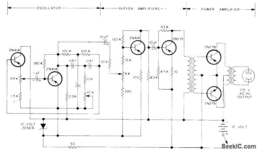
100W SINE AT 60Hz
The circuit primarily comprises a 60-Hz sine-wave oscillator featuring a 10K frequency-control potentiometer, two buffering stages, and a push-pull power amplifier. This design effectively addresses the noise issues associated with square-wave inverters, particularly when powering a 115-V radio receiver or...
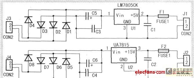
The single-phase sine wave frequency conversion stabilized voltage supply is designed and made
When the input voltage is between 198-242V, the average load current should be maintained at 0.5-1A, and the output voltage must remain at 15V with an error margin of less than 5%. The design and measurement of the stabilized voltage...
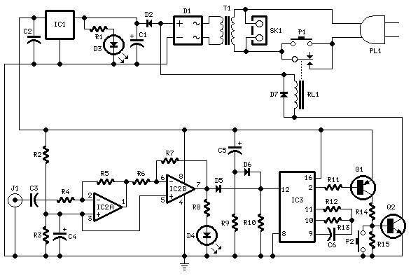
amplifier timer
This circuit deactivates an amplifier or any other device when a low-level audio signal at its input is absent for at least 15 minutes. By pressing P1, the device is powered on, allowing any appliance connected to SK1 to operate....
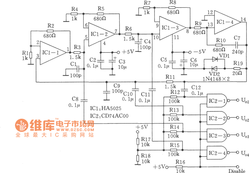
High-performance quadrature sine wave type oscillator circuit
Many RC oscillators utilize advanced circuits within the phase shift unit. These circuits employ voltage feedback amplifiers, whose gain decreases significantly at high frequencies and ceases when high frequency is not attained. The variation in the phase characteristics of the...
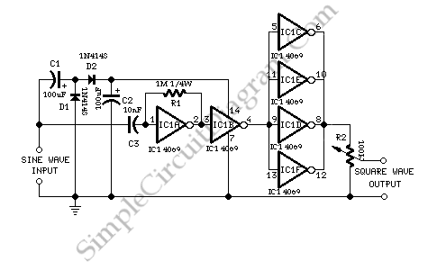
Self Powered Sine Wave to Square Converter
This circuit utilizes a single active component, the 4069 IC, to convert sine waves into square waves without requiring an external power source. It is designed for testing audio instruments.
The circuit leverages the characteristics of the 4069 IC, which is...
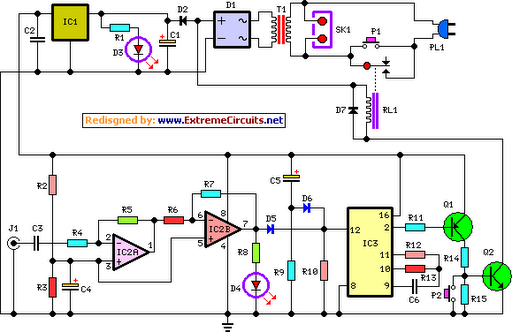
Amplifier Timer Circuit Schematic
This circuit deactivates an amplifier or any connected device when a low-level audio signal is absent at its input for at least 15 minutes. Activating switch P1 powers the device, enabling operation of any appliance connected to SK1. The input...
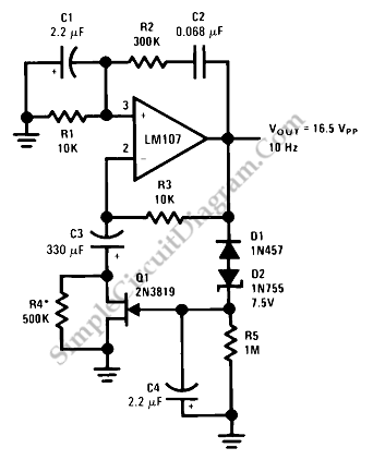
Sine Wave Oscillator
This is a sine wave oscillator circuit, also known as an amplitude-stabilized sine-wave oscillator. It can provide a high purity sine wave output.
The sine wave oscillator circuit is designed to generate a stable and high-quality sine wave output, which is...
DC-Coupled Audio Amplifier Circuit
This design circuit for audio amplifiers with DC coupling to the load is not commonly used today, despite its clear advantages. One advantage is the elimination of the need for a second (symmetric) power supply, and another is the improved...
generating a sine wave
After disappointing results with a transformer-based component tester, there is an interest in generating a ±10 V sine wave at approximately 50 Hz using minimal components. While an ATmega microcontroller could achieve this, it may be considered excessive, requiring significant...