


Parallel high-speed current driver circuit diagram OPA660
#OPA660
#current driver
#high-speed
#parallel circuit
#transistor
#signal processing
#amplifier
#analog circuit
#voltage control
#electronics
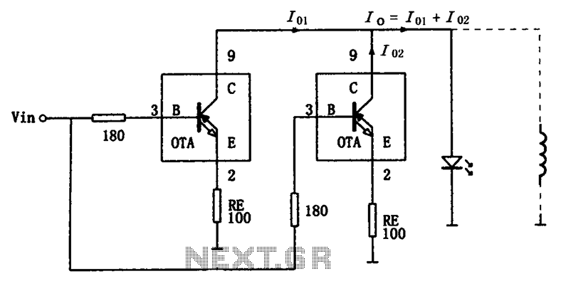
Description: The high-speed parallel current drive circuit utilizes the OPA660 operational transconductance amplifier (OTA). An input signal, Vin, is connected to a 180-ohm resistor equivalent device at the base (pin 3) of the OPA660. The collector (pin 8) is directly connected to the load. This configuration allows the circuit to provide current to the load, effectively doubling the current flowing through a single OTA. The OPA660 has a maximum output current of 15mA, while the parallel configuration can deliver a maximum output current of 30mA. For applications requiring even higher current, multiple OPA660 op-amps can be connected in parallel to achieve the desired load current. The 180-ohm external resistor at the base serves to limit the input signal, preventing self-oscillation of the amplifier and reducing peaking in frequency response. Additionally, a negative feedback resistor (RE), which can range from tens to several hundred ohms, is connected to the emitter. This resistor enhances the dynamic performance, linearity, and stability of the amplifier's input impedance, although it may lead to a reduction in the OTA's transconductance. Adjusting the resistance of RE enables fine-tuning of the output current.
The high-speed parallel current drive circuit is designed for applications that require precise control of output current while maintaining high-speed performance. The OPA660 OTA is specifically chosen for its ability to deliver significant output current, making it suitable for driving various loads, including capacitive and resistive components. The input signal, Vin, is effectively conditioned by the 180-ohm resistor, which mitigates the risk of self-oscillation that could compromise circuit stability. This resistor also plays a crucial role in shaping the frequency response of the amplifier, ensuring that the circuit operates efficiently across the desired frequency range.
In parallel configurations, the OPA660s work cohesively to provide the necessary current without exceeding individual device limits. This approach not only enhances the overall output capability but also ensures redundancy, as the failure of one OTA does not significantly impact the performance of the entire circuit. The inclusion of the negative feedback resistor, RE, contributes to the circuit's robustness by stabilizing the gain and improving linearity. However, it is essential to select the appropriate value for RE, as it directly influences the transconductance of the OTA, thereby affecting the output current. The careful design of this circuit allows for versatility in applications, from audio amplification to signal conditioning in communication systems, where high-speed and high-current drive capabilities are paramount. As shown for the high-speed parallel current drive circuit. Input signal Vin have been added 180 resistor equivalent device OPA660 special OTA transistor base B (pin 3), the co llectors C (pin 8) connected directly, and connected with the load, while providing current to the load, thus the current flowing through a single OTA twice the load, because the OTA OPA660 maximum output current of 15mA, while the parallel circuit provides a maximum output current up to 30mA. When you need more current, multiple OPA660 op amps in parallel, in order to obtain the desired load current.
Input (B pole) 180 external resistor having a limiting effect, while preventing self-oscillation occurs amplifier and reduce the phenomenon peaking frequency characteristics. Connected to the emitter of the negative feedback resistor RE (tens of ohms to several hundred ohms) can increase the number of dynamic index linear amplifier input impedance and stability, but the OTA transconductance will decline, it can be seen, RE appropriately changing the resistance can adjust the size of the output current.
The high-speed parallel current drive circuit is designed for applications that require precise control of output current while maintaining high-speed performance. The OPA660 OTA is specifically chosen for its ability to deliver significant output current, making it suitable for driving various loads, including capacitive and resistive components. The input signal, Vin, is effectively conditioned by the 180-ohm resistor, which mitigates the risk of self-oscillation that could compromise circuit stability. This resistor also plays a crucial role in shaping the frequency response of the amplifier, ensuring that the circuit operates efficiently across the desired frequency range.
In parallel configurations, the OPA660s work cohesively to provide the necessary current without exceeding individual device limits. This approach not only enhances the overall output capability but also ensures redundancy, as the failure of one OTA does not significantly impact the performance of the entire circuit. The inclusion of the negative feedback resistor, RE, contributes to the circuit's robustness by stabilizing the gain and improving linearity. However, it is essential to select the appropriate value for RE, as it directly influences the transconductance of the OTA, thereby affecting the output current. The careful design of this circuit allows for versatility in applications, from audio amplification to signal conditioning in communication systems, where high-speed and high-current drive capabilities are paramount. As shown for the high-speed parallel current drive circuit. Input signal Vin have been added 180 resistor equivalent device OPA660 special OTA transistor base B (pin 3), the co llectors C (pin 8) connected directly, and connected with the load, while providing current to the load, thus the current flowing through a single OTA twice the load, because the OTA OPA660 maximum output current of 15mA, while the parallel circuit provides a maximum output current up to 30mA. When you need more current, multiple OPA660 op amps in parallel, in order to obtain the desired load current.
Input (B pole) 180 external resistor having a limiting effect, while preventing self-oscillation occurs amplifier and reduce the phenomenon peaking frequency characteristics. Connected to the emitter of the negative feedback resistor RE (tens of ohms to several hundred ohms) can increase the number of dynamic index linear amplifier input impedance and stability, but the OTA transconductance will decline, it can be seen, RE appropriately changing the resistance can adjust the size of the output current.
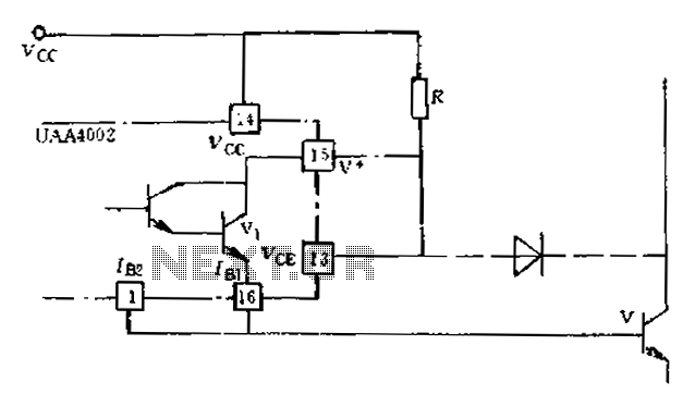
Anti-saturation function delete circuit schematics
Anti-saturation devices have been removed from the UAA4002 routine applications. The base current of the switching transistor, which is driven by another transistor, is automatically adjusted. This adjustment allows the power transistors to operate in critical saturation. However, when the...
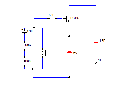
SIMPLE DELAY TIMER FOR ONE MINUTE
A simple transistorized one-minute delay timer circuit. It does not include any complex or critical components. This circuit can generate a time delay of approximately one minute. When the switch (preferably a push-button type) is pressed, the LED turns on...
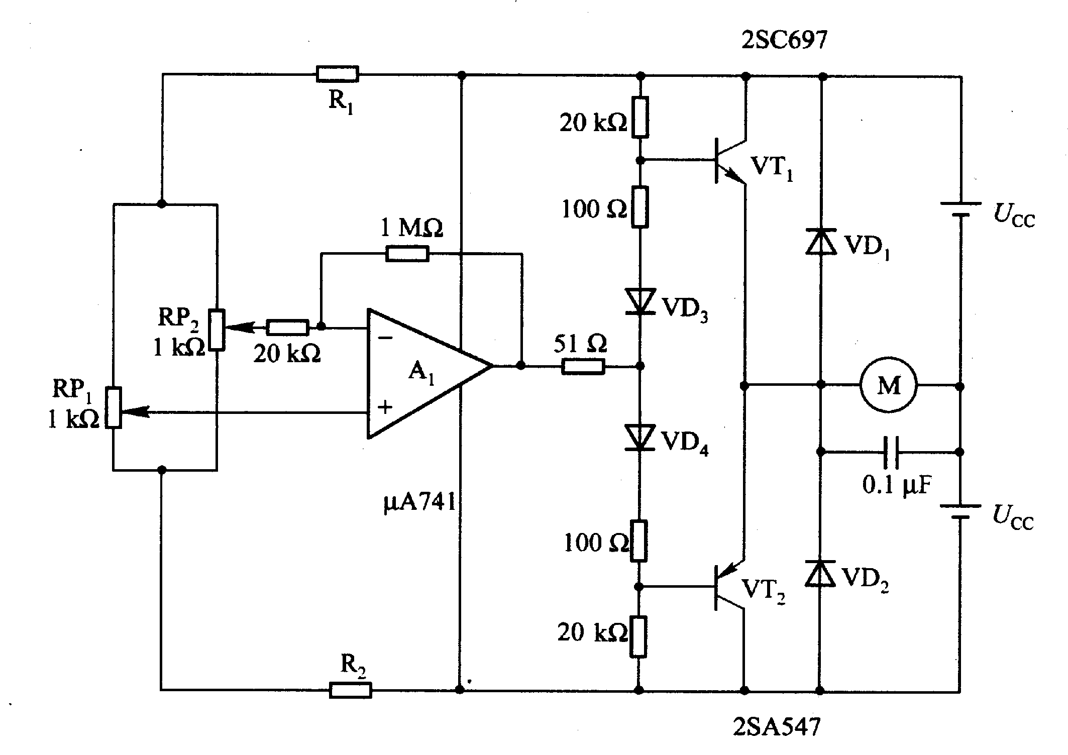
Motor time division control circuit composed of transistor and NE555
Figure 2-32 (a) illustrates the time control diagram for a motor operated by switch S1. When S1 is set to position 1, the power driver circuit supplies current to the motor, enabling it to run. When S1 is switched to...

Transistor Ignition
This transistor ignition circuit enhances vehicle starting and ensures smoother engine operation, especially at both high and low RPMs. It contributes to lower fuel consumption, reduced emissions, and decreased maintenance costs. The system promotes economical and electronic driving.
The transistor ignition...
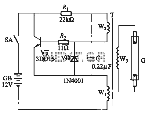
A five inverter circuit
A self-excited transistor inverter circuit is designed for improved performance and features a relatively simple schematic. It is suitable for driving fluorescent lamps with a power rating between 8 to 40 watts. This inverter can operate stably even when the...
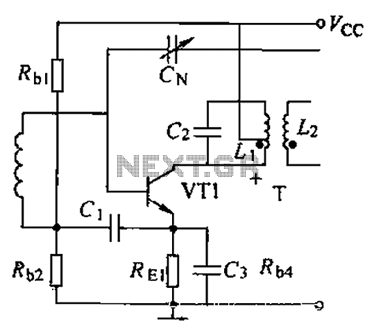
Common intermediate frequency amplifier circuit having a circuit and on the radio
A common intermediate frequency amplifier circuit is presented, along with its components and parameters. The reference values for the components are as follows: 1) Transistors: VT1 to 3DG19, Vcc = 6V. 2) Resistance values: R1 = 50 kΩ, R2 =...
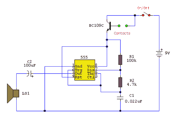
water activated alarm
Under dry conditions, the transistor will not have any bias current and will be completely off. However, when the probes become wet, the transistor will conduct, triggering the alarm. An On/Off switch is included, and it is important to use...
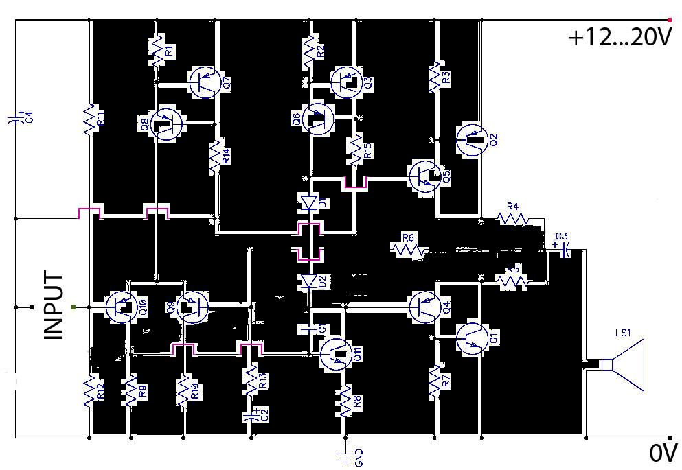
AB Transistor Audio Power Amplifier
This is a Class AB transistor power amplifier. It is straightforward to construct, utilizing standard components, and is known for its stability and reliability. The entire circuit employs commonly available parts and can be easily assembled on a general-purpose board....
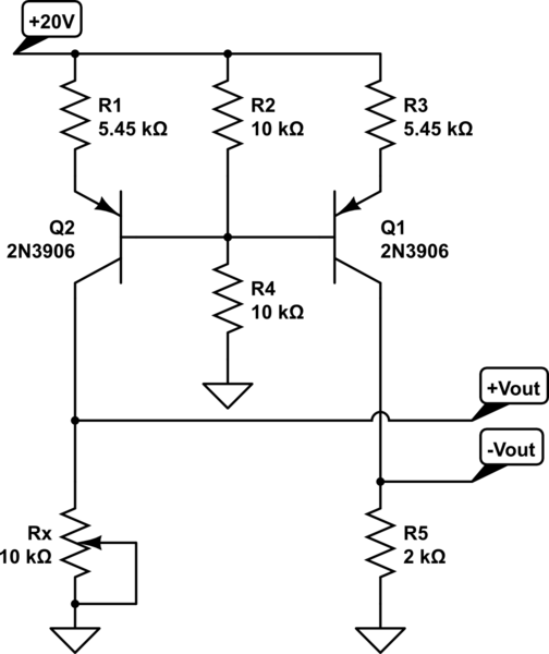
How do you make a shift/scale circuit using a transistor resistors and a voltage source
A functional circuit utilizing an operational amplifier (op-amp); however, the instructor indicated that op-amps can be challenging to work with and provided transistors as an alternative.
Operational amplifiers (op-amps) are versatile components commonly used in various electronic circuits for amplification,...