


Potentiometer-Position V/F Converter
#AD652IC
#voltage-to-frequency converter
#potentiometer
#signal conversion
#analog circuits
#frequency output
#synchronized converter
#position sensing
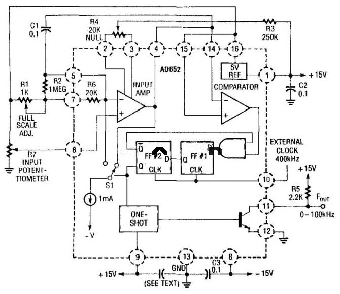
Description: In this application, an AD652 integrated circuit (IC) is utilized in a synchronized voltage-to-frequency (V/F) converter that takes its input from the position of a potentiometer. This setup can represent the position of a mechanical component, weight, size, etc., providing a 0-to-100 kHz output in relation to the 0-to-5 V output from the potentiometer.
The AD652 IC is designed to convert an analog voltage signal into a corresponding frequency signal. In this specific application, the potentiometer serves as a variable resistor, allowing for the adjustment of the input voltage from 0 to 5 V. As the position of the potentiometer is altered, the voltage output changes proportionally, which the AD652 interprets to generate a frequency output that ranges from 0 Hz to 100 kHz.
The circuit typically consists of the AD652 connected to the potentiometer, with the output frequency being measured or utilized in further electronic components or systems. The configuration may include additional passive components such as resistors and capacitors to stabilize the circuit and filter any noise that may affect the accuracy of the frequency output.
To ensure proper functionality, the power supply for the AD652 must be within the recommended voltage range, and the reference voltage should be stable to maintain accuracy in the conversion process. The output frequency can be monitored using a frequency counter or fed into a microcontroller for further processing, enabling applications in various fields such as robotics, automation, and measurement systems where precise position sensing is required.
Overall, the synchronized V/F converter utilizing the AD652 offers a reliable solution for translating analog voltage signals into frequency outputs, making it suitable for a wide range of applications where positional feedback is necessary. In this application, an AD652IC is used in a synchronized V/F converter that derives its input from th e position of a potentiometer. This can represent a position of a mechanical component, weight, size, etc., to give a 0-to-100-kHz output versus the O-to-5-V output from the potentiometer.
The AD652 IC is designed to convert an analog voltage signal into a corresponding frequency signal. In this specific application, the potentiometer serves as a variable resistor, allowing for the adjustment of the input voltage from 0 to 5 V. As the position of the potentiometer is altered, the voltage output changes proportionally, which the AD652 interprets to generate a frequency output that ranges from 0 Hz to 100 kHz.
The circuit typically consists of the AD652 connected to the potentiometer, with the output frequency being measured or utilized in further electronic components or systems. The configuration may include additional passive components such as resistors and capacitors to stabilize the circuit and filter any noise that may affect the accuracy of the frequency output.
To ensure proper functionality, the power supply for the AD652 must be within the recommended voltage range, and the reference voltage should be stable to maintain accuracy in the conversion process. The output frequency can be monitored using a frequency counter or fed into a microcontroller for further processing, enabling applications in various fields such as robotics, automation, and measurement systems where precise position sensing is required.
Overall, the synchronized V/F converter utilizing the AD652 offers a reliable solution for translating analog voltage signals into frequency outputs, making it suitable for a wide range of applications where positional feedback is necessary. In this application, an AD652IC is used in a synchronized V/F converter that derives its input from th e position of a potentiometer. This can represent a position of a mechanical component, weight, size, etc., to give a 0-to-100-kHz output versus the O-to-5-V output from the potentiometer.
Qualitative Analysis of Analog Circuits
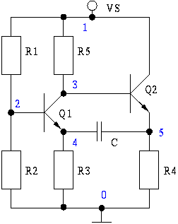
At the beginning of the design process, the designer must determine which circuit structure is appropriate for a specific purpose. During this phase, numerical and symbolic analysis are of limited utility. There are no numerical values available for conventional simulations...
Using tap potentiometer loudness circuit
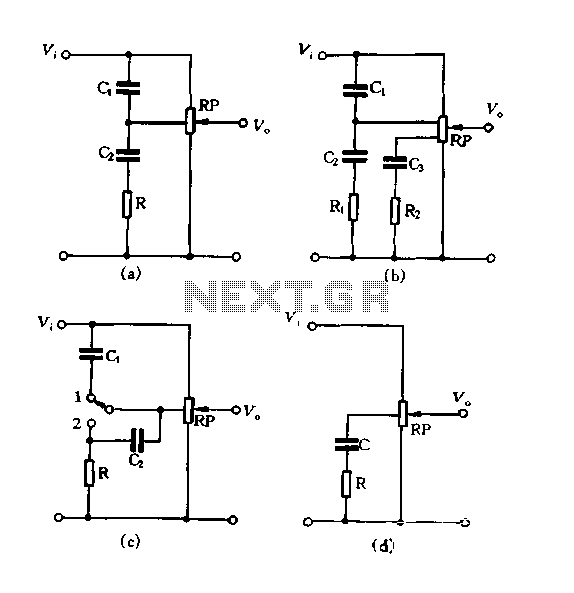
Figure 1.88 illustrates the loudness control circuit utilizing multiple taps on a potentiometer. In Figure (A), the connection is made between the tap and the potentiometer's input, along with the ground. An RC compensation network is employed, where the slide...
DPP adds versatility to VFC
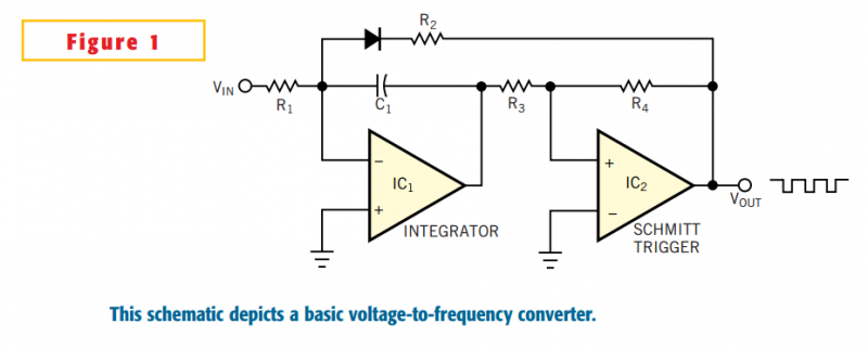
The basic VFC (voltage-to-frequency converter) in Figure 1 comprises an integrator (IC1) and a Schmitt-trigger circuit (IC2). The integrator converts the dc input voltage, VIN, to a linear voltage ramp, and the Schmitt trigger sets the limits of the integrator's...
Voltage-To-Frequency Converter I
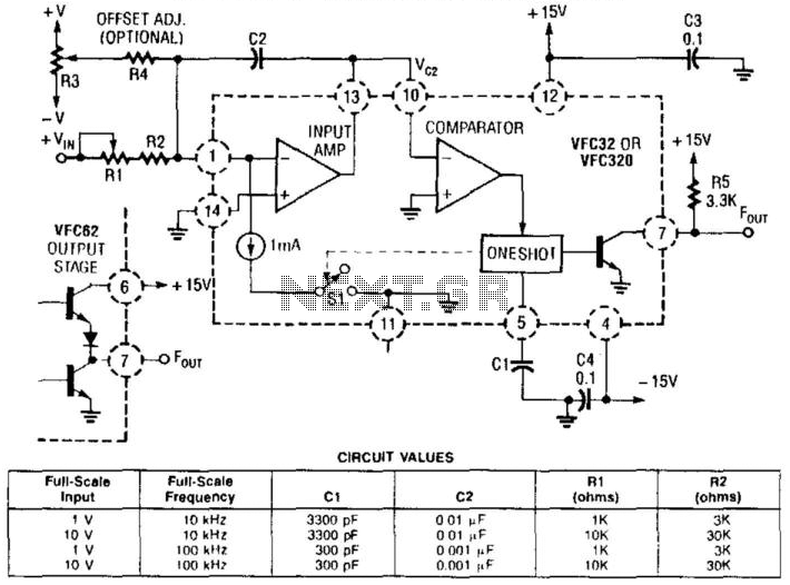
This voltage-to-frequency converter utilizes a Burr-Brown VFC 32 integrated circuit (IC) and requires minimal components. The circuit values are illustrated in the accompanying figure. This charge-balanced voltage-to-frequency (V/F) converter employs either a VFC32 or a VFC320 IC. The positive charge...
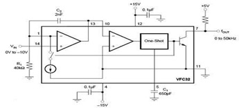
Negative Input Voltage Circuit using Voltage-to-Frequency Converter
The circuit diagram of a voltage-to-frequency (V/F) converter is presented, designed to handle negative input voltage. It employs the VFC32 voltage-to-frequency converter, which is commonly utilized in various applications.
The V/F converter circuit is essential in converting an analog voltage signal...
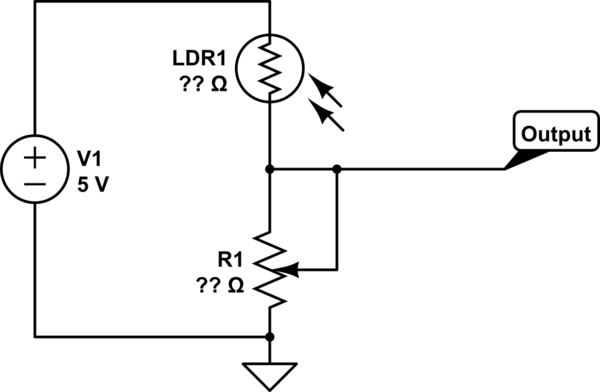
potentiometer Making an adjustable resistance
This part of the circuit is isolated from any other component, except for the 5V and ground connections. It includes LEDs and a shift register, which may not interact significantly. The LDR (Light Dependent Resistor) is utilized solely as a...
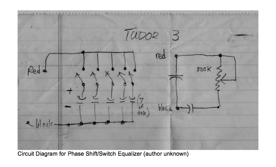
music circuit
This circuit allows for the adjustment of resistance using a potentiometer and the adjustment of capacitance by opening or closing switches. By manipulating the configuration of these switches, various combinations can be achieved to obtain different effective capacitance values. It...
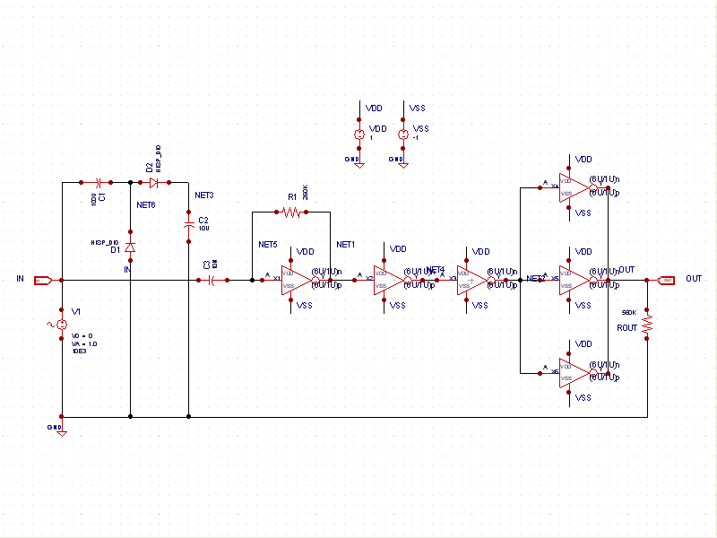
Sine to Square Wave Converter
This schematic example demonstrates a sinusoidal voltage input at a frequency of 10 kHz, which is converted to a square wave using an inverter-based circuit. The VDD and VSS rails are connected to +1V and -1V, respectively. The control file...
Sine to Square Wave Converter
This schematic example demonstrates a sinusoidal voltage input at a frequency of 10 kHz, which is converted to a square wave using an inverter-based circuit. The VDD and VSS rails are connected to +1V and -1V, respectively. The control file...