


Power operational amplifier integrated circuit
#current drive
#servo system
#motor control
#phase shift
#servo loop
#amplifier
#integrated circuit
#current proportional
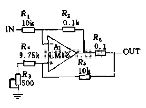
Description: In a servo system, the current drive connection is frequently utilized. The output current (IOUT) is proportional to the input channel number (y). Using the current drive mode can mitigate issues caused by the motor's large inductance, which induces a phase shift and aids in stabilizing the servo loop.
In the context of servo systems, the implementation of a current drive connection serves a critical role in enhancing performance and stability. The relationship between the output current (IOUT) and the input channel number (y) is a fundamental aspect of this configuration, as it establishes a direct proportionality that is essential for accurate control of the servo mechanism.
The current drive mode is particularly advantageous when dealing with motors that exhibit significant inductance. Inductive components can introduce phase shifts that complicate the control dynamics of the servo loop. By employing a current drive approach, these phase shifts can be effectively countered, leading to improved stability and responsiveness of the servo system. This stabilization is vital for applications that demand precise positioning and speed control, such as robotics, CNC machinery, and automated systems.
In a typical schematic for a servo system utilizing current drive, key components include a current sensor, a feedback loop, and control circuitry. The current sensor monitors the output current (IOUT), providing real-time data to the control circuitry. This feedback is crucial for adjusting the input signal based on the current draw of the motor, ensuring that the system operates within desired parameters.
The control circuitry typically employs a PID (Proportional-Integral-Derivative) controller, which processes the input from the current sensor and adjusts the drive signal accordingly. By fine-tuning the PID parameters, the system can achieve optimal performance, minimizing overshoot and settling time while maintaining stability despite the challenges posed by inductive loads.
Overall, the implementation of a current drive connection in servo systems represents a sophisticated approach to managing the complexities of motor control, particularly in high-performance applications where precision and stability are paramount.When used in the servo system, often using the current drive connection. Figure 11-1, the output current IOUT and the input channel number y.. It is proportional. Current drive mode can be reduced because the motor has a large inductance causes a phase shift, help stabilize the servo loop.
In the context of servo systems, the implementation of a current drive connection serves a critical role in enhancing performance and stability. The relationship between the output current (IOUT) and the input channel number (y) is a fundamental aspect of this configuration, as it establishes a direct proportionality that is essential for accurate control of the servo mechanism.
The current drive mode is particularly advantageous when dealing with motors that exhibit significant inductance. Inductive components can introduce phase shifts that complicate the control dynamics of the servo loop. By employing a current drive approach, these phase shifts can be effectively countered, leading to improved stability and responsiveness of the servo system. This stabilization is vital for applications that demand precise positioning and speed control, such as robotics, CNC machinery, and automated systems.
In a typical schematic for a servo system utilizing current drive, key components include a current sensor, a feedback loop, and control circuitry. The current sensor monitors the output current (IOUT), providing real-time data to the control circuitry. This feedback is crucial for adjusting the input signal based on the current draw of the motor, ensuring that the system operates within desired parameters.
The control circuitry typically employs a PID (Proportional-Integral-Derivative) controller, which processes the input from the current sensor and adjusts the drive signal accordingly. By fine-tuning the PID parameters, the system can achieve optimal performance, minimizing overshoot and settling time while maintaining stability despite the challenges posed by inductive loads.
Overall, the implementation of a current drive connection in servo systems represents a sophisticated approach to managing the complexities of motor control, particularly in high-performance applications where precision and stability are paramount.When used in the servo system, often using the current drive connection. Figure 11-1, the output current IOUT and the input channel number y.. It is proportional. Current drive mode can be reduced because the motor has a large inductance causes a phase shift, help stabilize the servo loop.
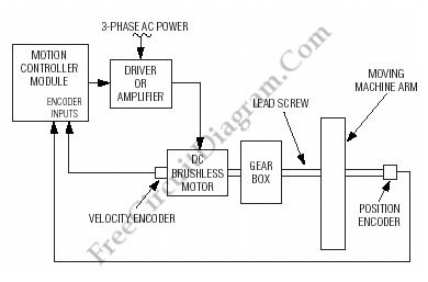
Motion (Motor) Control Servo System Block Diagram
Below is a block diagram of modern automated systems that incorporate closed-loop feedback for motion control. They typically include a servo system that consists of various components.
Automated systems utilizing closed-loop feedback mechanisms are designed to enhance precision and responsiveness in...
Stereo audio power amplifier circuit using TDA2822
Circuit stereo TDA2822 audio power amplifier circuit schematics. In this series, the TDA2822M IC is utilized as the primary amplifier. Additionally, alternatives such as KA2209 and NJM2073 can also be employed.
The TDA2822 audio power amplifier circuit is designed to provide...
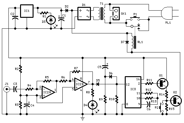
Amplifier Timer
This circuit turns off an amplifier or any other device when a low-level audio signal fed to its input is absent for 15 minutes at least. Pushing P1, the device is switched on, feeding any appliance connected to SK1. Input...
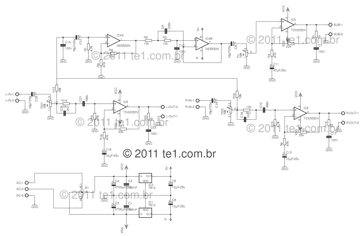
circuit power audio amplifier with
This circuit is a complete application for a 2.1 amplifier system, featuring two satellite speakers for TDA and one subwoofer. It is commonly used in commercial applications to enhance the audio output of computers using a stereo amplifier along with...
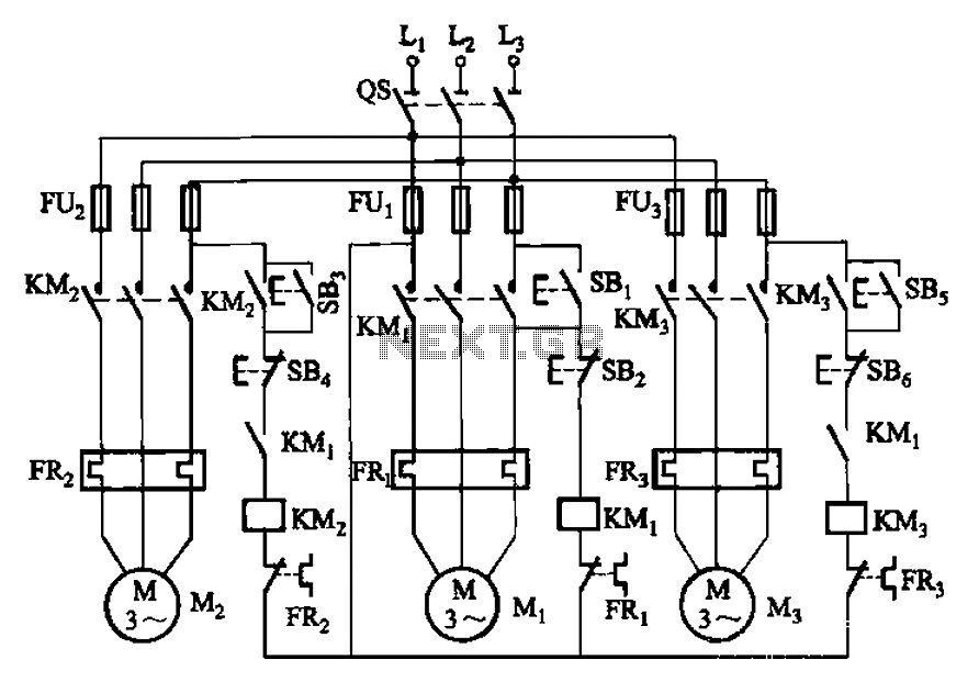
Three motor control circuit start and stop sequence requirements
The circuit shown in Figure 3-89 illustrates a system where starting motor M1 allows motors M2 and M3 to initiate operation. Upon shutdown, motor Mz can be stopped first; however, once motor M1 is stopped (by pressing switch SB2), motors...
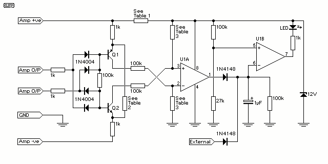
Amplifier Clipping Indicator
At some stage, we will all find ourselves pushing hi-fi equipment just a little too hard, and if lucky, will just find that the sound has become "dirty". If this happens too often or is too severe, tweeters are the...
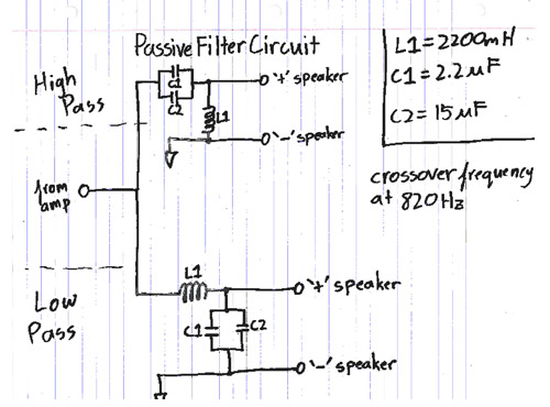
iPod/MP3 Mini Speaker System
Listen and share music wherever you go with the mini speaker system project. This project allows for music playback in various locations such as dorms, cubicles, or the beach. It serves as an excellent introduction to circuit systems, featuring an...
Motorized Video Camera Mount
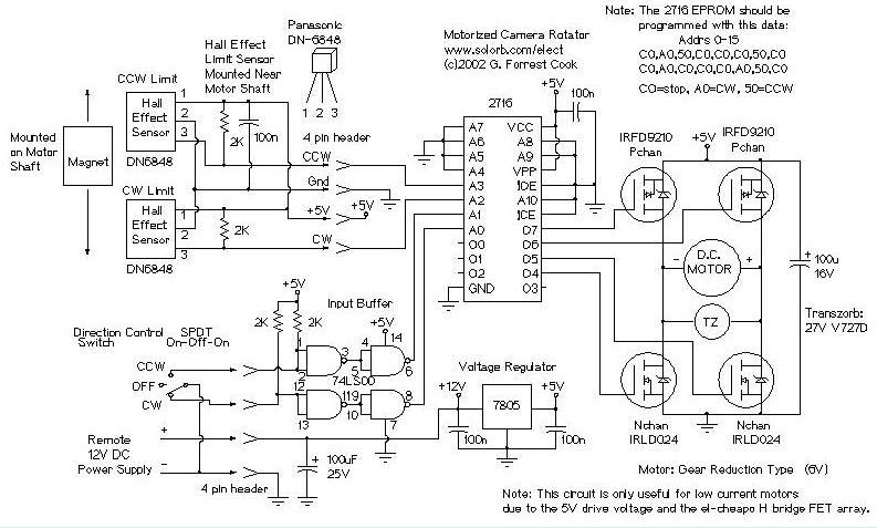
The camera rotator circuit utilizes a 2716 EPROM to store a logic value table that governs the motor driver (H-bridge) circuit. The schematic illustrates the EPROM data. By employing the EPROM, a significant number of discrete gates are eliminated. The...
USB Powered Audio Power Amplifier
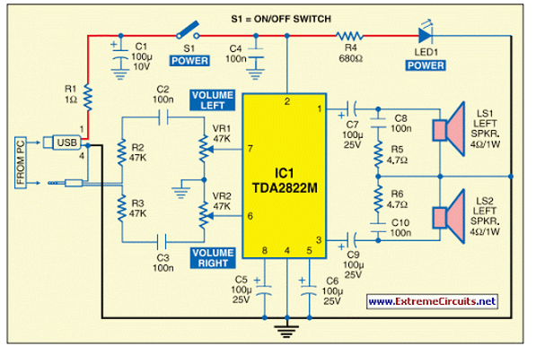
This circuit of multimedia speakers for PCs features a single-chip design, operates on a low-voltage power supply, is compatible with USB power, and allows for easy heat dissipation.
The multimedia speaker circuit is designed to enhance audio output for personal computers,...