


Programmable bandpass using twin-t bridge
#bandpass
#twin-t bridge
#programmable
#FET
#frequency control
#gain control
#operational amplifier
#filter
#voltage control
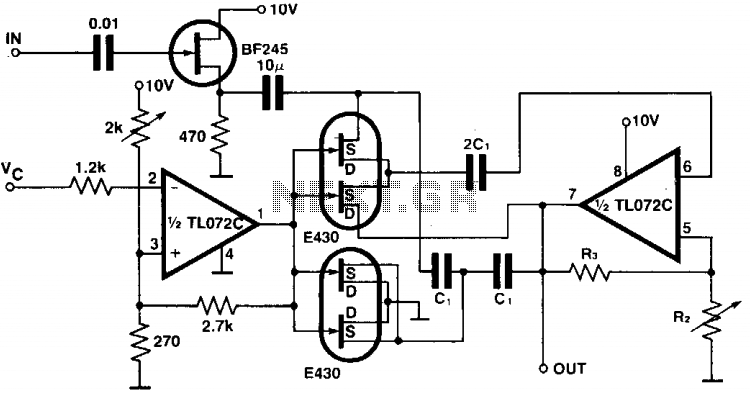
Description: The circuit provides a programmable bandpass filter where both the cutoff frequency and gain (A) can be controlled independently. In the twin-T bridge configuration, the resistors R and R/2 are replaced by two double FETs, with the channel resistance of the first FET in series and the channel resistances of the second FET in parallel to simulate the resistance R/2. Both of these resistors are controlled by a voltage (Vc) that ranges from 0 V to approximately 1 V. The gain of the circuit is determined by the resistors R2 and R3.
The described circuit employs a programmable bandpass filter architecture, utilizing a twin-T bridge configuration for effective frequency selection. The independent control of the cutoff frequency and gain is a significant advantage, allowing for versatile applications in signal processing.
The twin-T bridge typically consists of a combination of resistors and capacitors that determine the frequency response. In this design, traditional resistors R and R/2 are substituted with double FETs, enhancing the circuit's programmability and responsiveness. The first FET operates in series, contributing to the overall resistance, while the second FET is configured in a parallel arrangement to emulate the desired resistance of R/2. This arrangement allows for finer control over the circuit's characteristics.
The control voltage (Vc), varying between 0 V and 1 V, directly influences the channel resistances of the FETs, thereby adjusting the cutoff frequency of the bandpass filter. This feature enables the circuit to adapt to different signal conditions and requirements dynamically.
The gain of the circuit is managed through resistors R2 and R3, which are critical in setting the amplification level of the output signal. By selecting appropriate values for these resistors, the user can achieve the desired gain, further enhancing the circuit's flexibility. This design is particularly useful in applications where precise control over frequency and gain is essential, such as in audio processing, communication systems, and instrumentation.
In summary, this programmable bandpass filter circuit represents an advanced approach to signal processing, leveraging FET technology for improved performance and adaptability. The ability to independently control both cutoff frequency and gain makes it an invaluable tool in various electronic applications.The circuit gives a programmable bandpass where both the cut-over frequency and the gain, A, are controlled independently. In the twin-T bridge the resistors R and R/2 are replaced by two double FETs, 430, the channel resistance of the first one in the series, the channel resistances of the second one are in parallel as to stimulate the resistance R/2.
Both these resistors are controlled by Vc which ranges from 0 V to about 1 V. The gain of the circuit is set by means of the resistors R2 and R3.
The described circuit employs a programmable bandpass filter architecture, utilizing a twin-T bridge configuration for effective frequency selection. The independent control of the cutoff frequency and gain is a significant advantage, allowing for versatile applications in signal processing.
The twin-T bridge typically consists of a combination of resistors and capacitors that determine the frequency response. In this design, traditional resistors R and R/2 are substituted with double FETs, enhancing the circuit's programmability and responsiveness. The first FET operates in series, contributing to the overall resistance, while the second FET is configured in a parallel arrangement to emulate the desired resistance of R/2. This arrangement allows for finer control over the circuit's characteristics.
The control voltage (Vc), varying between 0 V and 1 V, directly influences the channel resistances of the FETs, thereby adjusting the cutoff frequency of the bandpass filter. This feature enables the circuit to adapt to different signal conditions and requirements dynamically.
The gain of the circuit is managed through resistors R2 and R3, which are critical in setting the amplification level of the output signal. By selecting appropriate values for these resistors, the user can achieve the desired gain, further enhancing the circuit's flexibility. This design is particularly useful in applications where precise control over frequency and gain is essential, such as in audio processing, communication systems, and instrumentation.
In summary, this programmable bandpass filter circuit represents an advanced approach to signal processing, leveraging FET technology for improved performance and adaptability. The ability to independently control both cutoff frequency and gain makes it an invaluable tool in various electronic applications.The circuit gives a programmable bandpass where both the cut-over frequency and the gain, A, are controlled independently. In the twin-T bridge the resistors R and R/2 are replaced by two double FETs, 430, the channel resistance of the first one in the series, the channel resistances of the second one are in parallel as to stimulate the resistance R/2.
Both these resistors are controlled by Vc which ranges from 0 V to about 1 V. The gain of the circuit is set by means of the resistors R2 and R3.
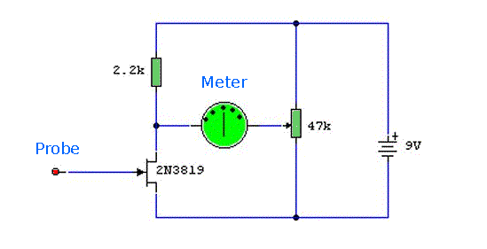
static detector negative ion detector
A sensitive detector for static electricity is based on a single Field Effect Transistor (FET). It can also be utilized to detect the presence of negative ions or to test a negative ion generator. This circuit takes advantage of the...
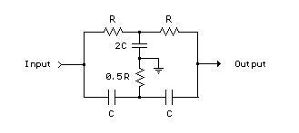
Twin-T RC Notch Filter
The two T-notch filter can be utilized to block unwanted frequencies or, when incorporated into an operational amplifier, function as a bandpass filter. The notch frequency occurs when the capacitive reactance equals the resistance (Xc = R), and if these...
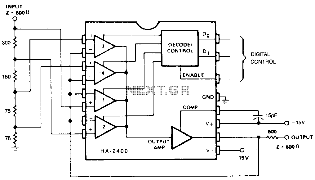
Programmable-attenuator
This circuit functions to divide the input signal by a chosen constant (1, 2, 4, 8, etc.). Although T, Z, or L sections could be utilized in the input attenuator, this is unnecessary since the amplifier loading is minimal, and...

FET Preamplifier Circuit
A Field Effect Transistor (FET) is an amplifying device where the output current is influenced by the input voltage. The FET preamplifier described here is sensitive.
The Field Effect Transistor (FET) operates by utilizing an electric field to control the flow...
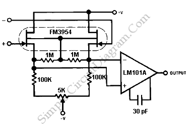
FET Op Amp
The FM3954 monolithic dual provides an ideal low-offset and low-drift buffer function for the LM101A operational amplifier. It operates effectively over its bias current range.
The FM3954 is a dual operational amplifier designed to serve as a buffer for the LM101A,...
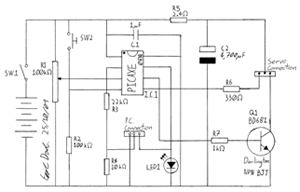
Programmable time-lapse camera controller
This project involves creating a programmable camera controller using basic hand tools and a digital camera. By utilizing components that are commonly found at home, the overall costs can be minimized. A servomotor can be repurposed from a radio-controlled model,...
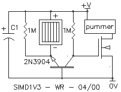
Wilf Rigter`s SIMD1 V3
The SIMD1 V3 is very similar to the NPN flavor of SIMD1 V2, but with the addition of a FET on the output line. This makes life easier for its attached load (since there's no need here for something that...
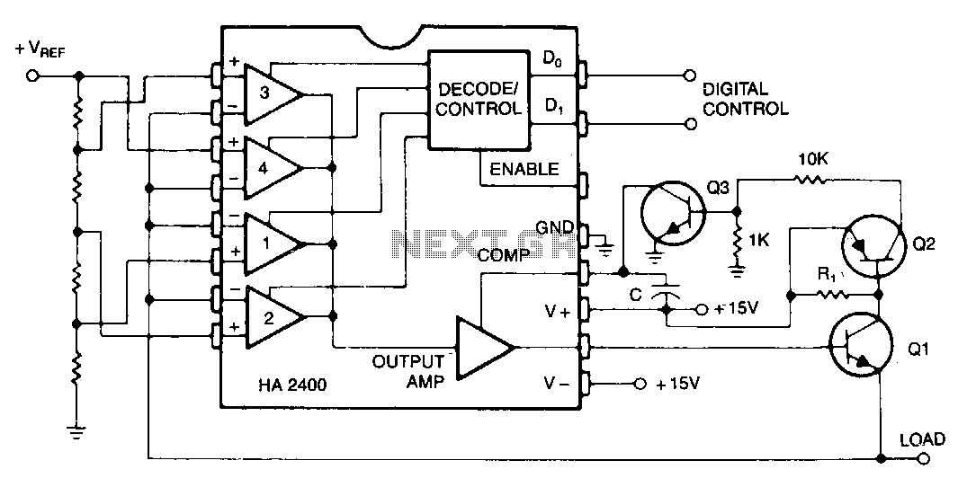
Programmable-power-supply
Many systems require one or more relatively low-current voltage sources that can be programmed to a few predetermined levels. The circuit presented generates positive output levels but can be modified for negative or bipolar outputs. Q1 serves as the series...
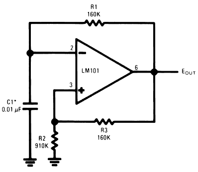
operational amplifier op amp oscillator
The timing capacitor (C1) generates multiple time constants, facilitating substantial voltage fluctuations at the input, attributable to the LM101's extensive input voltage range. It is advisable to decrease the value of resistor R2 and to increase the capacitance of C1...