


schematic dac0800 introduction
#DAC0800
#op-amp
#analog voltage
#microcontroller
#speaker
#alarm
#digital to analog converter
#5V
#signal isolation
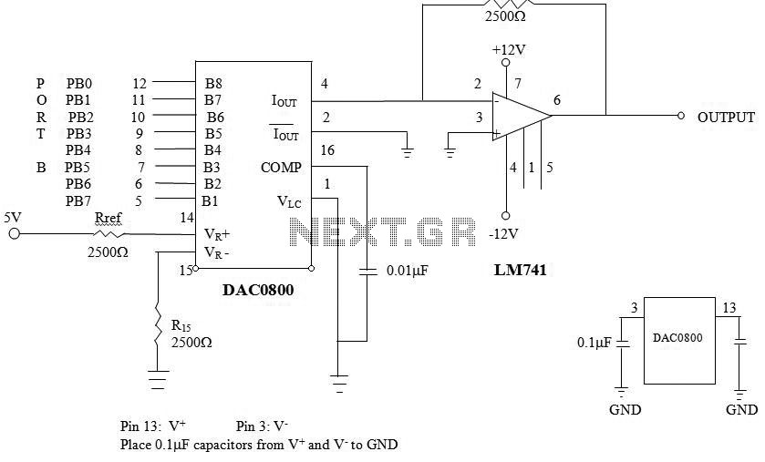
Description: The analog voltage is amplified and isolated from the controller circuit using an operational amplifier (Op-Amp) to ensure compatibility with the alarming device. In this circuit, a speaker, which operates on 5V, is utilized as the alarming device. A Digital-to-Analog Converter (DAC) is employed to convert the digital data from the microcontroller into an analog signal for the alarming device. An Op-Amp 741 is used at the output of the DAC to amplify and isolate the analog voltage from the controller circuit. The DAC0800 is chosen for high-speed digital-to-analog conversion. In scenarios where lower conversion rates are acceptable, an alternative method for digital-to-analog conversion can be utilized. For example, a square wave can be input into a low-pass filter with a cutoff frequency significantly lower than the square wave's repetition rate. Fourier analysis indicates that only the average value of the square wave will pass through the filter. By adjusting the duty cycle of the square wave, the average value can be modified. Consequently, the combination of a low-pass filter and output compare functions can create a simple D/A converter suitable for slowly varying signals. A program can be written to use the low-pass filter as a D/A converter, accepting a voltage between 0V and 5V, and generating a 10KHz square wave with a variable duty cycle to achieve the desired output voltage. The output compare functions should be utilized to generate this square wave. Measurements of Rref can be taken with an ohmmeter, and the circuit should be connected as illustrated. The voltage across Vref can be measured to calculate IFS. The program can be executed for various voltages to analyze the results.
The circuit described involves several critical components and configurations to achieve the desired functionality. The Op-Amp 741 is a versatile operational amplifier that provides gain and isolation, ensuring that the output signal is compatible with the 5V speaker used as an alarming device. The DAC0800, a high-performance digital-to-analog converter, facilitates rapid conversion of digital signals from the microcontroller into analog voltages, which are necessary for driving the speaker.
In addition to the primary components, the circuit employs a low-pass filter to smooth the output of a square wave generated by the microcontroller. The filter's cutoff frequency is strategically set to allow only the average value of the square wave to pass through, effectively transforming it into an analog signal. The variable duty cycle of the square wave is adjusted to control the output voltage, providing flexibility in the alarming signal's amplitude.
The operational setup requires careful measurement and calibration. The reference resistor (Rref) plays a crucial role in determining the output current (IFS), and it should be measured accurately to ensure proper functioning of the circuit. The voltage across Vref is a key parameter that influences the performance of the DAC, and it should be monitored throughout the testing phase to validate the circuit's response to varying input voltages.
By executing the program designed to manipulate the low-pass filter and output compare functions, the circuit can generate a range of analog voltages corresponding to different digital inputs. This capability allows for comprehensive analysis and fine-tuning of the alarming device's response, ensuring that it operates effectively within its specified voltage range.analog voltage get amplified and isolated from the controller circuit hence the Opamp circuit is used to provide the compatibility with the alarming device. In our circuit we have used a speaker as an alarming device which is operable on 5V. We have used the DAC to convert the digital data coming from the micro-controller to an analog alarming dev
ice, this is done by using an opamp 741 at the output of DAC so that the analog voltage get amplified and isolated from the controller circuit hence the Opamp circuit is used to provide the compatibility with the alarming device. In our circuit we have used a speaker as an alarming device which is operable on 5V. The DAC0800 provides high speed digital to analog conversion. When very low conversion rates can be used, another method of digital to analog conversion may suffice.
Consider a square wave which is input to a low pass filter, whose cutoff frequency is far below the repetition rate of the square wave. From Fourier analysis, only the average value of the square wave should pass through the filter. By varying the duty cycle for the square wave, the average value o f the wave can be changed. Therefore, a low pass filter and the output compare functions can be used together to form a simple D/A converter for slowly varying signals.
Write a program that uses the low pass filter in Figure 2 as a D/A converter. Accept a voltage, between 0V and 5. 0V, and use a 10KHz wave with variable duty cycle to produce the proper output voltage. The output compare functions should be used to generate the square wave. Measure Rref with an ohmmeter. Connect the circuit in Figure 1. Measure the voltage dropped across Vref and calculate IFS. Run the program for several voltages and analyze the results.
The circuit described involves several critical components and configurations to achieve the desired functionality. The Op-Amp 741 is a versatile operational amplifier that provides gain and isolation, ensuring that the output signal is compatible with the 5V speaker used as an alarming device. The DAC0800, a high-performance digital-to-analog converter, facilitates rapid conversion of digital signals from the microcontroller into analog voltages, which are necessary for driving the speaker.
In addition to the primary components, the circuit employs a low-pass filter to smooth the output of a square wave generated by the microcontroller. The filter's cutoff frequency is strategically set to allow only the average value of the square wave to pass through, effectively transforming it into an analog signal. The variable duty cycle of the square wave is adjusted to control the output voltage, providing flexibility in the alarming signal's amplitude.
The operational setup requires careful measurement and calibration. The reference resistor (Rref) plays a crucial role in determining the output current (IFS), and it should be measured accurately to ensure proper functioning of the circuit. The voltage across Vref is a key parameter that influences the performance of the DAC, and it should be monitored throughout the testing phase to validate the circuit's response to varying input voltages.
By executing the program designed to manipulate the low-pass filter and output compare functions, the circuit can generate a range of analog voltages corresponding to different digital inputs. This capability allows for comprehensive analysis and fine-tuning of the alarming device's response, ensuring that it operates effectively within its specified voltage range.analog voltage get amplified and isolated from the controller circuit hence the Opamp circuit is used to provide the compatibility with the alarming device. In our circuit we have used a speaker as an alarming device which is operable on 5V. We have used the DAC to convert the digital data coming from the micro-controller to an analog alarming dev
ice, this is done by using an opamp 741 at the output of DAC so that the analog voltage get amplified and isolated from the controller circuit hence the Opamp circuit is used to provide the compatibility with the alarming device. In our circuit we have used a speaker as an alarming device which is operable on 5V. The DAC0800 provides high speed digital to analog conversion. When very low conversion rates can be used, another method of digital to analog conversion may suffice.
Consider a square wave which is input to a low pass filter, whose cutoff frequency is far below the repetition rate of the square wave. From Fourier analysis, only the average value of the square wave should pass through the filter. By varying the duty cycle for the square wave, the average value o f the wave can be changed. Therefore, a low pass filter and the output compare functions can be used together to form a simple D/A converter for slowly varying signals.
Write a program that uses the low pass filter in Figure 2 as a D/A converter. Accept a voltage, between 0V and 5. 0V, and use a 10KHz wave with variable duty cycle to produce the proper output voltage. The output compare functions should be used to generate the square wave. Measure Rref with an ohmmeter. Connect the circuit in Figure 1. Measure the voltage dropped across Vref and calculate IFS. Run the program for several voltages and analyze the results.
Robo Atmega328p project
This project was designed to introduce a friend to microcontrollers and circuits using various functionalities and spare parts. A PS2 numpad was utilized as the key entry mechanism, which was found at a thrift store and included the necessary connector....
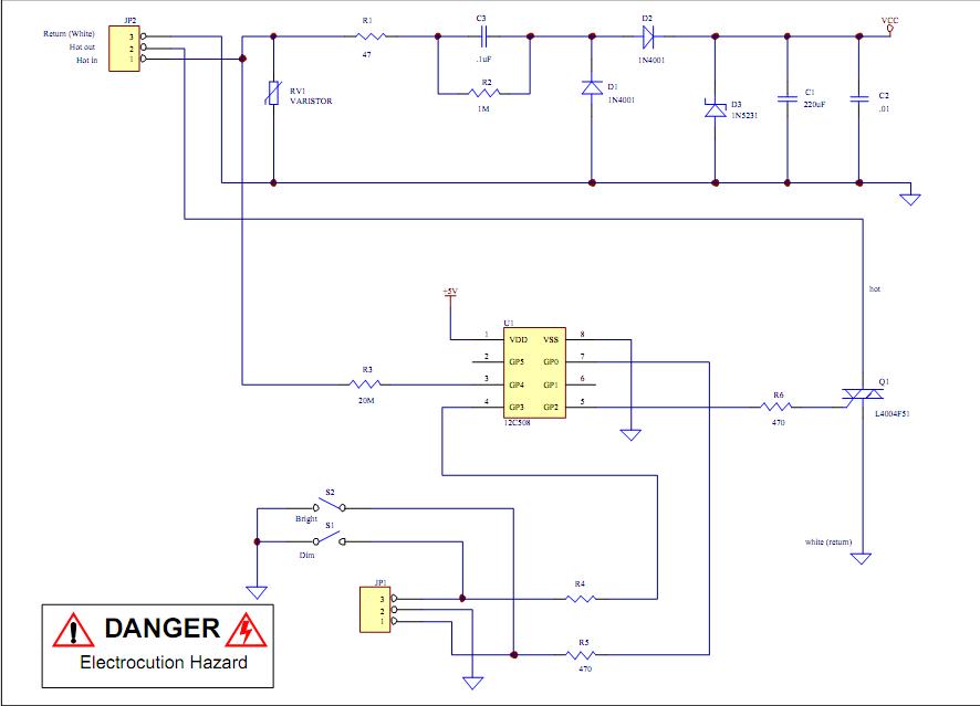
analog light dimmer circuit connected to microcontroller
Assistance is required to modify a light dimmer circuit connected to a PIC12C508 microcontroller. This circuit is designed for the...
The light dimmer circuit utilizing the PIC12C508 microcontroller serves to control the brightness of a light source through pulse width modulation...

Simple Multi-Tone Alarm Circuit
The figure illustrates the circuit diagram of a multi-tone alarm, which fundamentally operates as an amplifier circuit. The core component of this circuit is the dual.
The multi-tone alarm circuit is designed to produce various sound tones, enhancing its alerting capabilities....
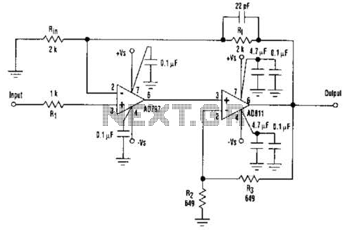
Fast Composite Amplifier Circuit
An ultra-low-noise, low-distortion operational amplifier, the AD797, is combined with the ADS 11 operational amplifier, which provides high bandwidth and a 100-mA output drive capability. This composite amplifier circuit is effective for driving high-resolution ADCs and ATE systems. The fast...
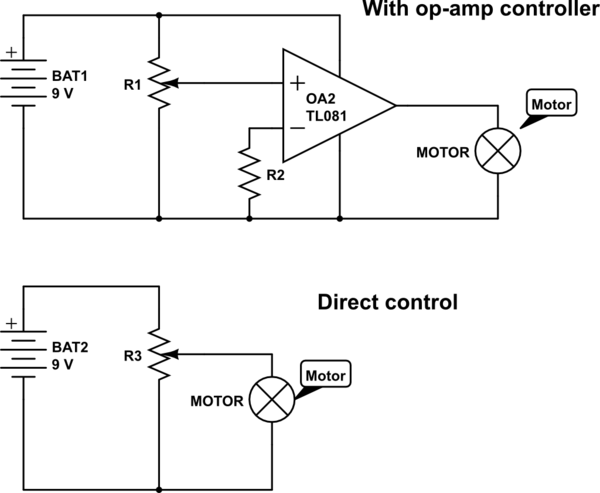
op amp op-amp vs direct control
A 100 Ohm resistor connected to a 4.5 Volt supply (using three AA batteries) allows a current of 45 mA. However, at the upper end of the current sweep, the effective current will be significantly higher due to the load...
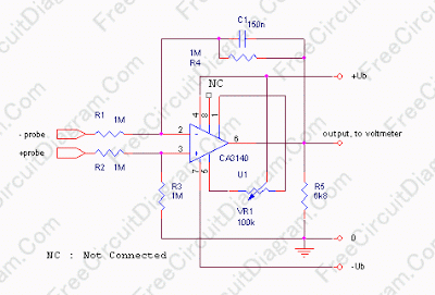
Single Differential Input Adapter for Digital Voltmeter
In some cases, a cogwheel input is necessary for voltage measurement. By utilizing a single operational amplifier, an adapter can be created to accommodate a differential input for a ground-referenced voltmeter. It is recommended to use 1% tolerance metal film...
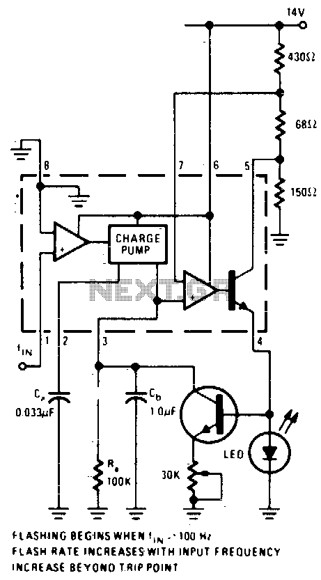
Overspeed indicator
An operational amplifier (op-amp) comparator is utilized to compare the output of a converter with a direct current (DC) threshold voltage. The circuit activates an LED when the input frequency surpasses 100 Hz. As the frequency increases, the average current...
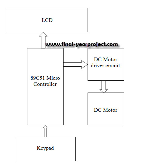
Speed Control of DC Motor using Microcontroller by using PWM ECE Project
This report details an electronic project focused on the speed control of a DC motor using a microcontroller and PWM (Pulse Width Modulation). The system integrates a microcontroller with an LCD, keypad, and a DC motor driver. The microcontroller generates...
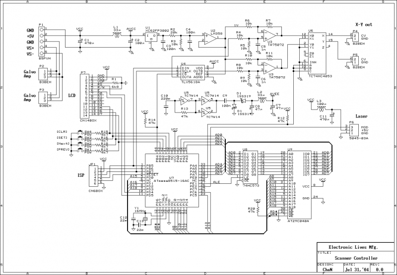
Home Built Laser Projector
This document outlines the servo amplifier and its circuit diagram. It describes a straightforward operational amplifier circuit that integrates both a power amplifier and a small signal amplifier on the same board. Care must be taken to avoid unintended coupling...