


Second-order active band stop filter circuit
#band-stop filter
#active filter
#op-amp
#signal processing
#frequency response
#second-order filter
#BEF
#analog circuit
#filter design
#electronics
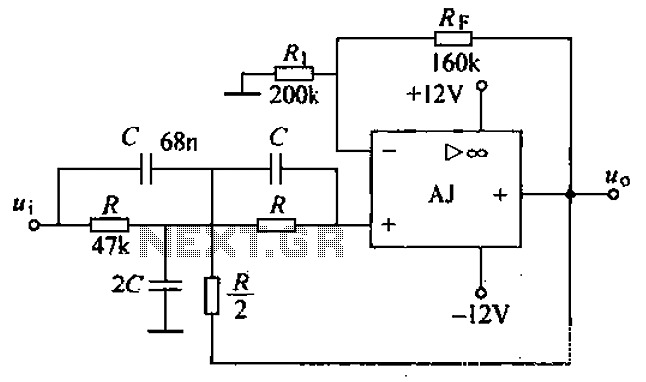
Description: A band-stop filter (BSF) utilizing an integrated operational amplifier is designed to suppress signals within a specific frequency band, allowing signals outside this band to pass with minimal attenuation. This configuration is achieved through a two-stage network, which employs a T-phase ratio arithmetic circuit to form a basic second-order active band-stop filter. The filter is represented in the accompanying figure, which illustrates the integrated operational amplifier configuration using a dual op-amp setup.
The band-stop filter (BSF) is a critical component in various electronic applications where it is necessary to eliminate unwanted frequencies while preserving the integrity of other signals. The design typically consists of a combination of resistors, capacitors, and operational amplifiers that work together to create a notch in the frequency response at the desired frequency range.
In this configuration, the operational amplifier serves as the active element, providing gain and allowing for precise control over the filter characteristics. The dual op-amp arrangement enhances the filter's performance by enabling the implementation of more complex filtering techniques, such as feedback and feedforward paths, which can improve stability and selectivity.
The two-stage network in the band-stop filter consists of a series of reactive components that define the filter's cutoff frequencies and the depth of attenuation at the notch frequency. The T-phase ratio arithmetic circuit plays a vital role in determining the phase response of the filter, ensuring that the output maintains the desired characteristics over the specified frequency range.
Overall, the integrated operational amplifier band-stop filter is an essential tool in signal processing, audio engineering, and communication systems, where it is crucial to eliminate specific interference while allowing other signals to pass through unaffected. The design's effectiveness is largely dependent on the precise selection of component values and the configuration of the operational amplifiers used in the circuit. Band-stop filter (BEF) integrated operational amplifier, such electrical road performance and a bandpass filter contrary, that in a certain band, the signal can not be (or has been greatly attenuated or suppressed), while in the remaining frequency Fan Wai, signals can be passed. After two-plus network level T-phase ratio arithmetic circuit, it constitutes the basic second-order active band-stop filter BEF.
Band stop filter as shown in FIG. FIG integrated operational amplifier AJ dual op amp
The band-stop filter (BSF) is a critical component in various electronic applications where it is necessary to eliminate unwanted frequencies while preserving the integrity of other signals. The design typically consists of a combination of resistors, capacitors, and operational amplifiers that work together to create a notch in the frequency response at the desired frequency range.
In this configuration, the operational amplifier serves as the active element, providing gain and allowing for precise control over the filter characteristics. The dual op-amp arrangement enhances the filter's performance by enabling the implementation of more complex filtering techniques, such as feedback and feedforward paths, which can improve stability and selectivity.
The two-stage network in the band-stop filter consists of a series of reactive components that define the filter's cutoff frequencies and the depth of attenuation at the notch frequency. The T-phase ratio arithmetic circuit plays a vital role in determining the phase response of the filter, ensuring that the output maintains the desired characteristics over the specified frequency range.
Overall, the integrated operational amplifier band-stop filter is an essential tool in signal processing, audio engineering, and communication systems, where it is crucial to eliminate specific interference while allowing other signals to pass through unaffected. The design's effectiveness is largely dependent on the precise selection of component values and the configuration of the operational amplifiers used in the circuit. Band-stop filter (BEF) integrated operational amplifier, such electrical road performance and a bandpass filter contrary, that in a certain band, the signal can not be (or has been greatly attenuated or suppressed), while in the remaining frequency Fan Wai, signals can be passed. After two-plus network level T-phase ratio arithmetic circuit, it constitutes the basic second-order active band-stop filter BEF.
Band stop filter as shown in FIG. FIG integrated operational amplifier AJ dual op amp
All-analog automatic night light circuit
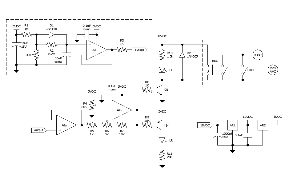
Approximately ten days ago, an all-linear automatic night light circuit was installed to control the lights in the living room. The circuit comprises three operational amplifiers (op-amps): two configured as voltage followers and one as a comparator. As depicted in...
Low-Cost Logarithmic Converter Using Opamp and Transistor
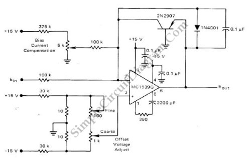
This low-cost logarithmic converter is constructed using an operational amplifier (op-amp) and a transistor. The circuit utilizes a Motorola MC1539G op-amp connected to a PNP transistor.
The logarithmic converter circuit is designed to convert linear input signals into logarithmic output signals,...
Triangular Wave Generator Using Op-amp
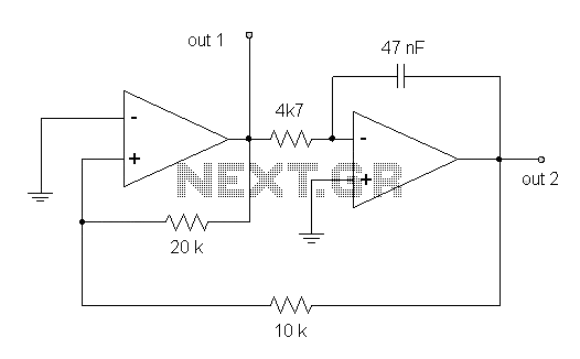
This circuit diagram illustrates a triangular wave generating circuit utilizing a pair of operational amplifiers (Op-Amps). The LM741 Op-Amp is recommended for this application. The first Op-Amp, located on the left, functions as a comparator, while the second Op-Amp on...
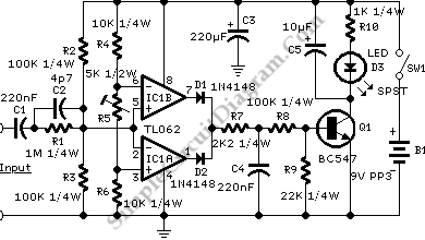
Audio Signal Clipping Indicator
A window comparator formed by two operational amplifiers packaged into IC1 is the heart of the circuit below. With this technique, we can detect precisely and symmetrically.
The window comparator circuit utilizes two operational amplifiers (op-amps) configured to create a defined...
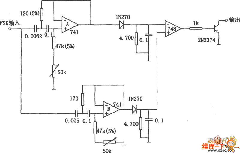
The frequency shift demodulator circuit composed of active filter
Replacing the LC modulation circuit with an active filter allows for the elimination of large and costly inductance coils in frequency shift key control demodulators. This approach not only reduces the size of the circuit but also enhances the performance...
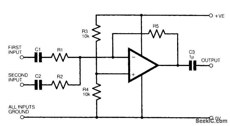
TWO CHANNEL AUDIO MIXER
The figure illustrates a fundamental two-channel operational amplifier (op-amp) mixer circuit. The gain for channel 1 is determined by the ratio of resistors R5 to R1, while for channel 2, it is determined by the ratio of R5 to R2....
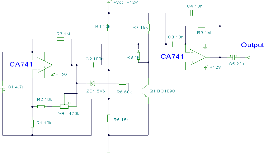
Metronome Circuit
This circuit utilizes two operational amplifiers (op-amps) to create a unique sound effect. The first op-amp, CA741, is configured as a standard astable multivibrator, generating timing pulses controlled by components C1, R2, and variable resistor VR1. The output from this...
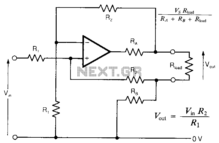
Safe-opamp-circuit
In intrinsically safe applications, it is sometimes necessary to separate sections of circuitry using resistors that limit current under fault conditions. The circuit presented offers an accurate analog output with effectively zero output impedance, despite the presence of resistors in...
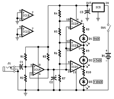
audio peak level indicator by op amp
No setup is required: if correct values are used for resistors R3 to R7, LED D1 will illuminate at 0 dB input (0.775V RMS), LED D2 at +5 dB input (1.378V RMS), and LED D3 at +10 dB (2.451V RMS)....