


Simulated inductor
#simulated inductor
#op-amp
#frequency response
#active device
#feedback
#instability
#Q factor
#RLC
#electronics simulation
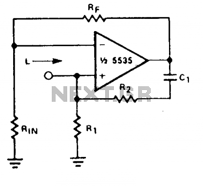
Description: With a constant current excitation, the voltage drop across an inductance increases with frequency. An active device whose output increases with frequency can be characterized as an inductance. The circuit exhibits this response with the effective inductance defined as L = R1R2C. The quality factor (Q) of this inductance is contingent upon Rj being equal to R2. However, the equal positive and negative feedback paths of the amplifier create a distinct possibility of instability at high frequencies. Therefore, R1 should always be slightly smaller than R2 to ensure stable operation.
In this circuit, the effective inductance is determined by the relationship of the resistors R1 and R2, along with the capacitor C. The expression L = R1R2C indicates that the inductance is a product of the resistors and capacitance, highlighting the interdependence of these components. The quality factor (Q) is a critical parameter that defines the performance of the inductive circuit, influencing both the bandwidth and resonance characteristics. When Rj is set equal to R2, it optimizes the Q factor, enhancing the circuit's responsiveness to frequency changes.
However, the feedback mechanisms within the amplifier must be carefully managed. The equal feedback paths can lead to oscillations or instability, particularly at higher frequencies where the gain of the circuit may increase significantly. To mitigate this risk, it is essential that R1 is maintained at a value slightly less than R2, which helps to stabilize the feedback loop and maintain consistent performance across the operating frequency range. This design consideration is crucial for applications requiring reliable inductive behavior without the adverse effects of instability.
In summary, this circuit design emphasizes the careful selection of component values to achieve desired inductive characteristics while ensuring stable operation, particularly in the presence of varying frequencies.With a constant current excitation, the voltage dropped across an inductance increases with frequency. Thus, an active device whose output increases with frequency can be characterized as an inductance. The circuit yields such a response with the effective inductance being equal to: L = R1R2C. The Q of this inductance depends upon Rj being equal to R2. At the same time, however, the positive and negative feedback paths of the amplifier are equal leading to the distinct possibility of instability at high frequencies.
R1 should therefore always be slightly smaller than R2 to assure stable operation.
In this circuit, the effective inductance is determined by the relationship of the resistors R1 and R2, along with the capacitor C. The expression L = R1R2C indicates that the inductance is a product of the resistors and capacitance, highlighting the interdependence of these components. The quality factor (Q) is a critical parameter that defines the performance of the inductive circuit, influencing both the bandwidth and resonance characteristics. When Rj is set equal to R2, it optimizes the Q factor, enhancing the circuit's responsiveness to frequency changes.
However, the feedback mechanisms within the amplifier must be carefully managed. The equal feedback paths can lead to oscillations or instability, particularly at higher frequencies where the gain of the circuit may increase significantly. To mitigate this risk, it is essential that R1 is maintained at a value slightly less than R2, which helps to stabilize the feedback loop and maintain consistent performance across the operating frequency range. This design consideration is crucial for applications requiring reliable inductive behavior without the adverse effects of instability.
In summary, this circuit design emphasizes the careful selection of component values to achieve desired inductive characteristics while ensuring stable operation, particularly in the presence of varying frequencies.With a constant current excitation, the voltage dropped across an inductance increases with frequency. Thus, an active device whose output increases with frequency can be characterized as an inductance. The circuit yields such a response with the effective inductance being equal to: L = R1R2C. The Q of this inductance depends upon Rj being equal to R2. At the same time, however, the positive and negative feedback paths of the amplifier are equal leading to the distinct possibility of instability at high frequencies.
R1 should therefore always be slightly smaller than R2 to assure stable operation.
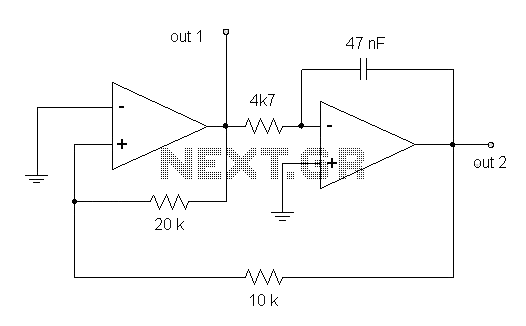
Triangular Wave Generator Using Op-amp
This circuit diagram illustrates a triangular wave generating circuit utilizing a pair of operational amplifiers (Op-Amps). The LM741 Op-Amp is recommended for this application. The first Op-Amp, located on the left, functions as a comparator, while the second Op-Amp on...
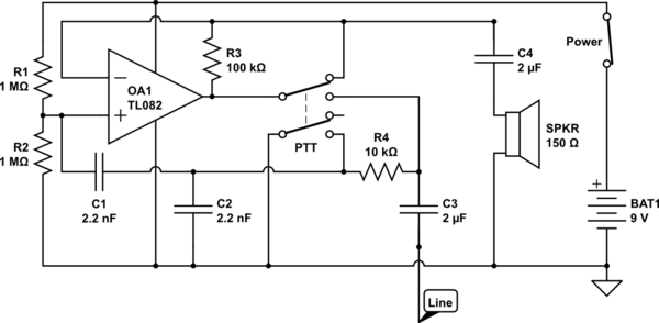
op amp Could someone help me understand this simple circuit
The circuit operates in receive mode, with the Push-To-Talk (PTT) switch enabling transmit mode. The speaker functions as both a microphone and a speaker. Most systems observed utilize a rocking armature transducer for the speaker. There is no base station...
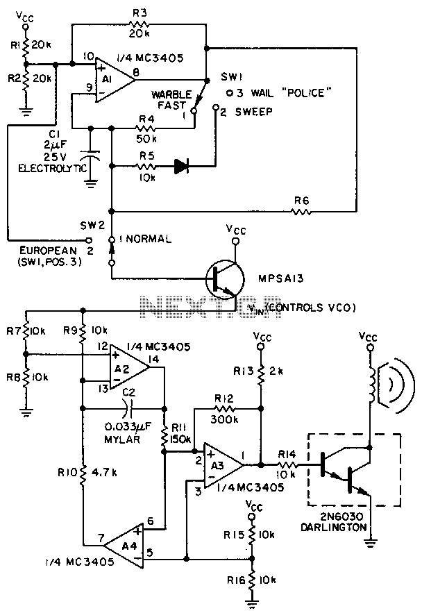
Linear-ic-siren
A low-frequency op-amp oscillator and a voltage-controlled oscillator (VCO), both configured using a single MC3405 dual op-amp and dual comparator, are the primary components in a siren circuit capable of producing various warbles and wails, or functioning as an audio...
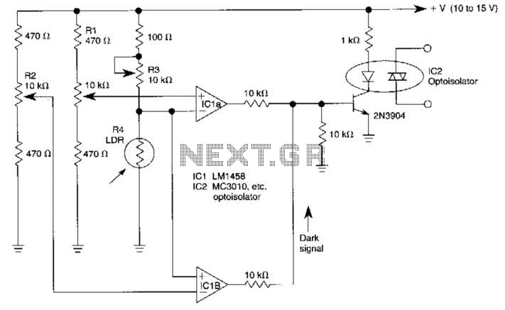
Combined Light-/Dark-Activated Switch Circuit
Two operational amplifiers are utilized in a bridge circuit configuration to detect high and low light levels. Potentiometer R2 adjusts the dark level, while resistor R1 controls the light level. Resistor R3 is configured so that approximately 1A of the...
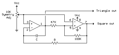
Audio Triangle Square Wave Generator Using Op-Amp
The circuit illustrates a straightforward triangle and square wave generator utilizing a common dual operational amplifier, the LM1558, capable of producing very low frequencies around 10 kHz. The time interval for one half-cycle is approximately determined by the product of...

op amp Why do some of my IE converter circuits have a large offset voltage
The inverting input is maintained at a low level via a 10K resistor when the circuit is powered on but not in use. During measurement activities, including calibration measurements where the input is floating, this resistor is disconnected. The circuit...
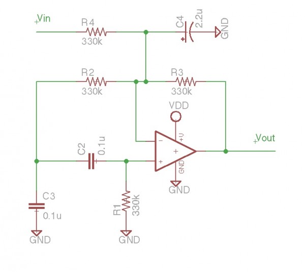
Karplus Strong Opamp Circuit
It is essentially an all-pass filter with two additional components: a capacitor and a resistor, which produces percussion sounds. A schematic of the unmodified all-pass filter circuit, a waveform captured via Audacity, and a short audio sample featuring a drum...
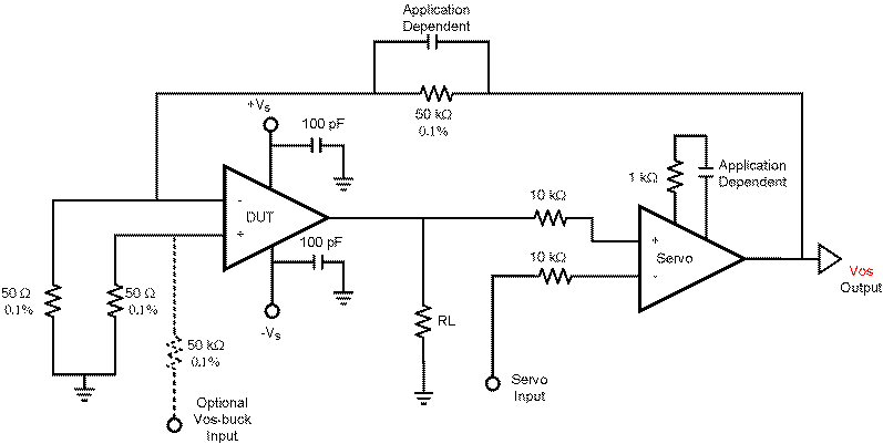
op amp How does this OP-AMP offset voltage measuring circuit work
This circuit is constructed using two LT1001 operational amplifiers (OP-AMPs), with the output of the OP-AMP saturating at +5V. The power supplies used are +5V and ground. According to the documentation, applying +1V to the "Servo Input" results in an...
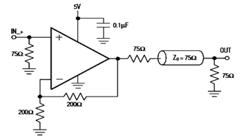
IC4030-4031 Typical Operating Circuit Schematic and Datasheet
The diagram below illustrates a typical operating circuit for the video line driver using the IC4030/4031 schematic. It incorporates the MAX4030E/MAX4031E, which are unity-gain stable operational amplifiers that offer high-speed performance, rail-to-rail outputs, and 15kV ESD protection, as stated in...