


Sine-wave shaper
#sine-wave
#CA3140
#op-amp
#voltage follower
#CA3019
#diode array
#signal conversion
#triangular wave
#function generator
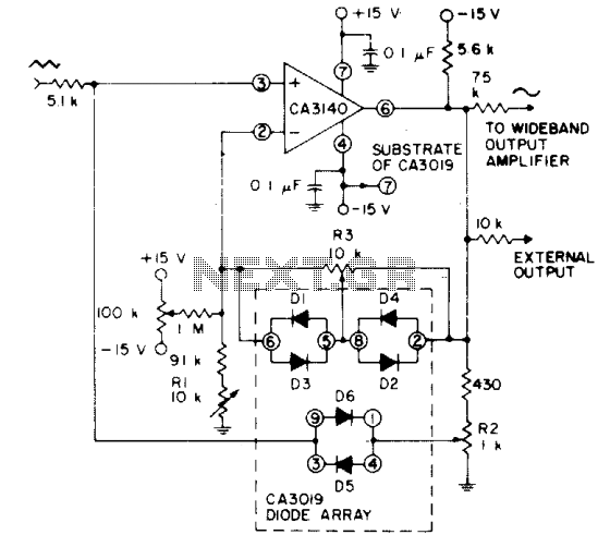
Description: Utilizes a CA3140 BiMOS operational amplifier configured as a voltage follower, along with diodes from a CA3019 array, to transform a triangular signal (such as that produced by a function generator) into a sine-wave output with a typical total harmonic distortion (THD) of less than 2%.
The circuit employs a CA3140 BiMOS operational amplifier, which is known for its high input impedance and low output impedance characteristics, making it ideal for voltage follower applications. The op amp is configured in a non-inverting configuration to ensure that the output voltage closely follows the input voltage, thereby providing a buffered output that maintains signal integrity.
The triangular waveform input, generated by a function generator, is fed into the non-inverting input of the CA3140. The output of the op amp is then connected to a diode array, specifically the CA3019. This array consists of multiple diodes configured to shape the waveform. The diodes allow for selective clipping and smoothing of the triangular waveform, effectively converting it into a sine wave.
The output from the diode array is then monitored, and adjustments can be made to the circuit components, such as the resistor values or diode selection, to optimize the output sine wave characteristics. The design aims for a total harmonic distortion (THD) of less than 2%, ensuring that the output signal maintains high fidelity and is suitable for applications requiring precision waveform generation.
Overall, this circuit exemplifies a practical approach to waveform shaping using operational amplifiers and diode arrays, demonstrating the versatility and effectiveness of analog components in signal processing applications.Uses a CA3140 BiMOS op amp as voltage follower, together with diodes from a CA3019 array, to convert a triangular signal (such as obtained from a function generator) to a sine-wave output with typical THD less than 2%.
The circuit employs a CA3140 BiMOS operational amplifier, which is known for its high input impedance and low output impedance characteristics, making it ideal for voltage follower applications. The op amp is configured in a non-inverting configuration to ensure that the output voltage closely follows the input voltage, thereby providing a buffered output that maintains signal integrity.
The triangular waveform input, generated by a function generator, is fed into the non-inverting input of the CA3140. The output of the op amp is then connected to a diode array, specifically the CA3019. This array consists of multiple diodes configured to shape the waveform. The diodes allow for selective clipping and smoothing of the triangular waveform, effectively converting it into a sine wave.
The output from the diode array is then monitored, and adjustments can be made to the circuit components, such as the resistor values or diode selection, to optimize the output sine wave characteristics. The design aims for a total harmonic distortion (THD) of less than 2%, ensuring that the output signal maintains high fidelity and is suitable for applications requiring precision waveform generation.
Overall, this circuit exemplifies a practical approach to waveform shaping using operational amplifiers and diode arrays, demonstrating the versatility and effectiveness of analog components in signal processing applications.Uses a CA3140 BiMOS op amp as voltage follower, together with diodes from a CA3019 array, to convert a triangular signal (such as obtained from a function generator) to a sine-wave output with typical THD less than 2%.
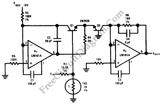
Anti-Log Converter
Anti-log or exponential generation involves rearranging logarithmic circuitry. The circuit diagram below illustrates the relevant circuitry.
Anti-logarithmic or exponential circuits are essential in various applications, particularly in signal processing and analog computing. These circuits typically utilize operational amplifiers (op-amps) configured in...
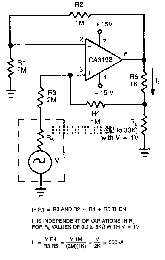
Bilateral-current-source
This circuit employs a CA3193 precision operational amplifier to provide a current that remains consistent regardless of variations in the load resistance (RL). By configuring the input resistance (RI) to be equal to resistance R3 and setting resistance R2 to...
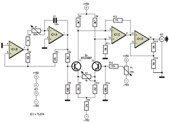
triangular wave oscillator
This design was developed to partially replace the well-known 8038 chip, which is no longer in production and therefore difficult to obtain. An existing design for driving a Linear Variable Differential Transformer (LVDT) sensor utilized the 8038 as a variable...
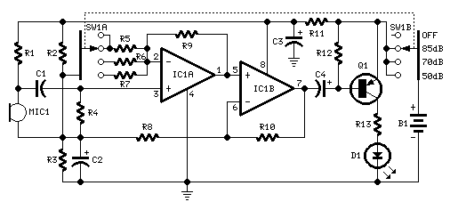
Room Noise Detector Schematic Circuit
This circuit is designed to signal the exceeding of a fixed threshold in room noise through a flashing LED. Three fixed levels are selectable: 50, 70, and 85 dB. Two operational amplifiers provide the necessary gain for sounds captured by...
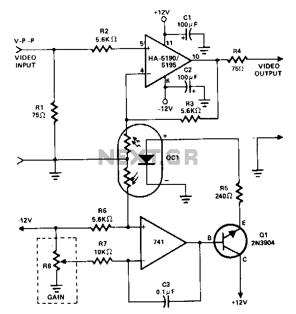
Dc-gain-controlled-video-amplifier
This amplifier utilizes a cascaded operational amplifier (op amp) integrator and a transistor buffer, Q1, to drive the gain control element. With a minor modification, the HA-5190/5195 stage is configured as a conventional non-inverting op amp and includes input and...
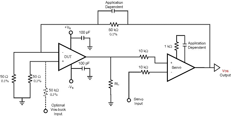
op amp How does this OP-AMP offset voltage measuring circuit work
This circuit is constructed using two LT1001 operational amplifiers (OP-AMPs), with the output of the OP-AMP saturating at +5V. The power supplies used are +5V and ground. According to the documentation, applying +1V to the "Servo Input" results in an...
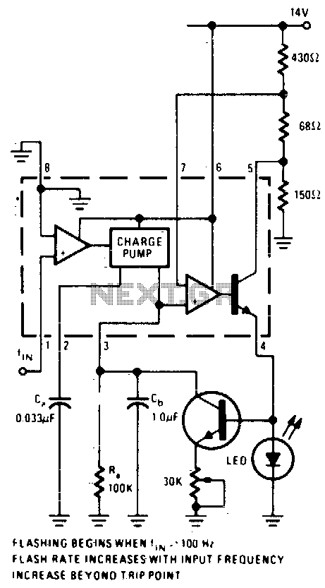
Overspeed indicator
An operational amplifier (op-amp) comparator is utilized to compare the output of a converter with a direct current (DC) threshold voltage. The circuit activates an LED when the input frequency surpasses 100 Hz. As the frequency increases, the average current...
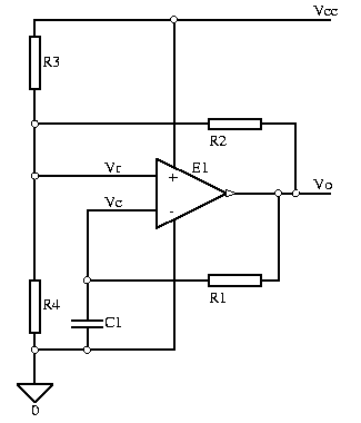
OP-AMP or comparator Astable multivibrator
Simulation schematic for an astable multivibrator. Parameters: Vcc = 24V, Vol = 1V, Voh = 21V. The power supply is Vcc, with connections from Vcc to ground. The time constant is determined by R1 and the capacitor C1, where R1...
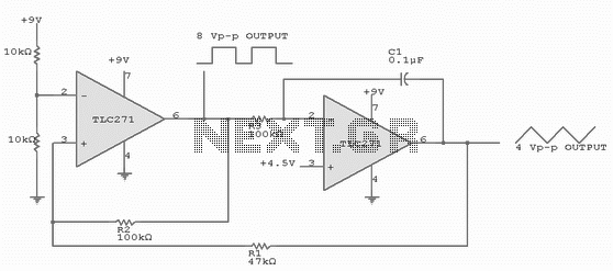
FUNCTION GENERATOR
The circuit has both square-wave and triangle-wave output. The left section is similar in function to a comparator circuit that uses positive feedback for hysteresis. The inverting input is biased at one-half the Vcc voltage by resistor R4 and R5....