


single cdta leads multiple filters
#CDTA
#active component
#filters
#bias current
#amplifier
#signal processing
#analog circuits
#filter responses
#electronic design
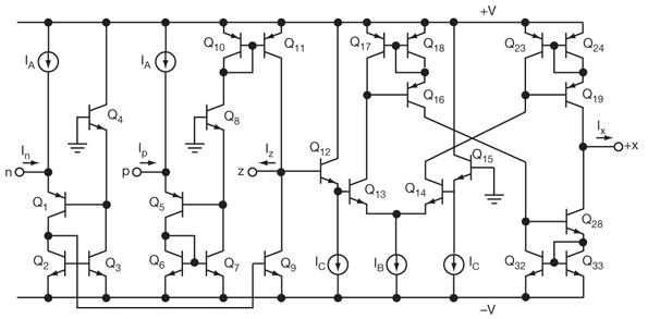
Description: A current differencing transconductance amplifier (CDTA) serves as an active component that can be utilized to create various filter responses. The selection of different filter characteristics is achieved by altering the bias current supplied to the amplifier.
The current differencing transconductance amplifier (CDTA) is a versatile active device widely used in analog signal processing applications. Its unique architecture allows for the implementation of various filter configurations, such as low-pass, high-pass, band-pass, and notch filters. The CDTA operates by converting input current signals into output voltage signals while maintaining high linearity and bandwidth.
In practical applications, the bias current is a critical parameter that influences the performance of the CDTA. By adjusting this bias current, the transconductance parameter of the amplifier can be modified, leading to changes in the filter's cut-off frequency and quality factor (Q). This adaptability makes the CDTA an excellent choice for designing tunable filters that can respond to varying signal conditions.
To implement a filter using a CDTA, the circuit typically includes resistive and capacitive elements arranged to create the desired frequency response. The input current is applied to the CDTA's current input terminals, and the output can be taken from the voltage output terminal. The feedback network, which may consist of resistors and capacitors, determines the filter characteristics, allowing for precise control over the filter's behavior.
In summary, the CDTA's ability to produce multiple filter responses through bias current adjustment, combined with its high performance in signal processing, makes it a valuable component in modern electronic circuit design. Its applications can be found in audio processing, communications, and instrumentation, where flexible and efficient filtering is essential.An active component, a CDTA, can be used as the basis for a variety of different filter responses, selecting the different responses by changing bias current to the amplifier..
The current differencing transconductance amplifier (CDTA) is a versatile active device widely used in analog signal processing applications. Its unique architecture allows for the implementation of various filter configurations, such as low-pass, high-pass, band-pass, and notch filters. The CDTA operates by converting input current signals into output voltage signals while maintaining high linearity and bandwidth.
In practical applications, the bias current is a critical parameter that influences the performance of the CDTA. By adjusting this bias current, the transconductance parameter of the amplifier can be modified, leading to changes in the filter's cut-off frequency and quality factor (Q). This adaptability makes the CDTA an excellent choice for designing tunable filters that can respond to varying signal conditions.
To implement a filter using a CDTA, the circuit typically includes resistive and capacitive elements arranged to create the desired frequency response. The input current is applied to the CDTA's current input terminals, and the output can be taken from the voltage output terminal. The feedback network, which may consist of resistors and capacitors, determines the filter characteristics, allowing for precise control over the filter's behavior.
In summary, the CDTA's ability to produce multiple filter responses through bias current adjustment, combined with its high performance in signal processing, makes it a valuable component in modern electronic circuit design. Its applications can be found in audio processing, communications, and instrumentation, where flexible and efficient filtering is essential.An active component, a CDTA, can be used as the basis for a variety of different filter responses, selecting the different responses by changing bias current to the amplifier..
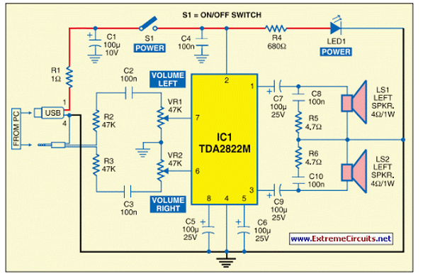
USB Powered Audio Power Amplifier
This circuit of multimedia speakers for PCs features a single-chip design, operates on a low-voltage power supply, is compatible with USB power, and allows for easy heat dissipation.
The multimedia speaker circuit is designed to enhance audio output for personal computers,...
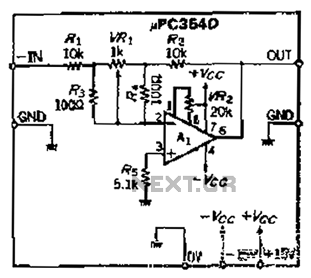
Precision polarity switching circuit by conventional elements
The loop gain of the operational amplifier (OP) is primarily influenced by the ratio of the input resistor to the feedback resistor. Consequently, any resistance error can lead to a corresponding gain error, which necessitates the use of high-precision resistors,...
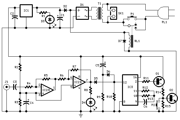
Amplifier Timer
This circuit turns off an amplifier or any other device when a low-level audio signal fed to its input is absent for 15 minutes at least. Pushing P1, the device is switched on, feeding any appliance connected to SK1. Input...
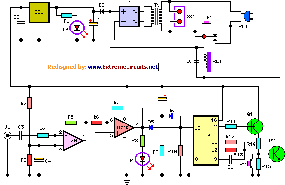
amplifier timer circuit schematic
This circuit deactivates an amplifier or any connected device when a low-level audio signal at its input is absent for at least 15 minutes. By pressing P1, the device is powered on, supplying power to any appliance connected to SK1....
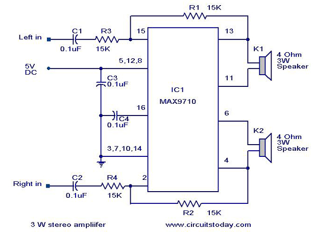
3 W Stereo amplifier using MAX 7910-Audio power amplifier circuit
An audio power amplifier circuit for a 3-watt stereo amplifier using the MAX 7910 IC is explained below.
The audio power amplifier circuit utilizing the MAX 7910 IC is designed to deliver a maximum output power of 3 watts per channel...
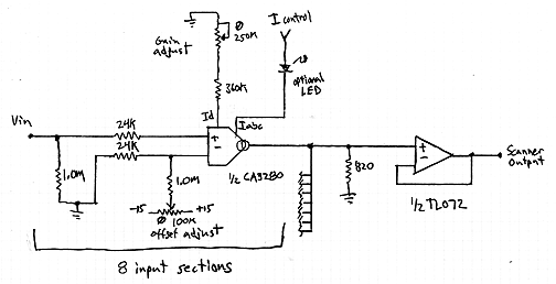
Interpolating Scanner Circuit
This design is for an interpolating scanner, a circuit featuring multiple signal inputs, a control voltage input, and a signal output. The output selectively transitions between inputs, smoothly fading from one to the next as the control voltage increases. A...
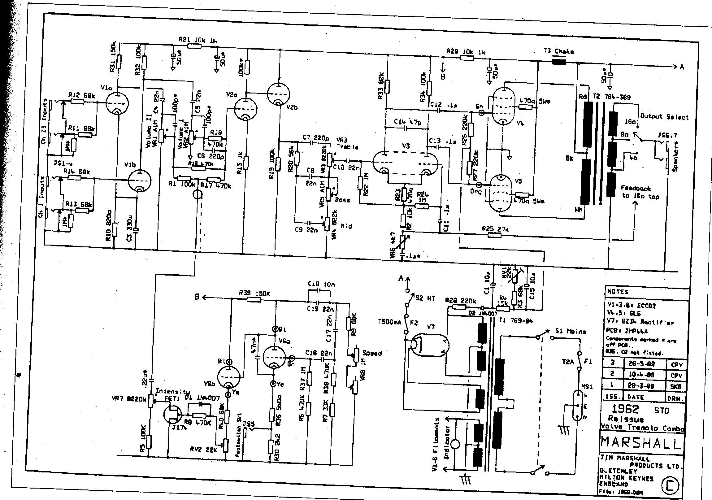
Marshall JTM-45 and 62 Bluesbreaker Reissue Modifications
The Sovtek 5881 tubes included in these amplifiers are low-quality and produce a corresponding sound. It is advisable to replace all tubes with a Sovtek GZ34, Valve Art or GT KT66 tubes, and Ei Gold preamp tubes. The KT66 tubes...

Small or Mini Audio Amplifier Circuit using TDA 7052 IC-Deliver 2 Watts
A compact audio amplifier circuit utilizing the TDA 7052 integrated circuit from Philips. This circuit is suitable for use as a pocket radio amplifier, delivering an output power of 2 watts.
The TDA 7052 is a low-voltage audio amplifier designed specifically...
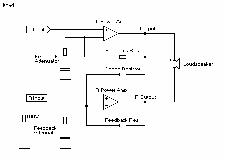
Amplifier Bridging
The primary advantage of this method of bridging is that no additional components are needed, which means that it is cheap, and there is no signal degradation from additional opamps in the circuit path. The results are at least as...