


Summing amplifier/ Inverting adder circuit using op amp 741
#op amp 741
#summing amplifier
#inverting adder
#signal processing
#voltage adder
#electronic circuits
#precision amplifier
#offset error
#audio
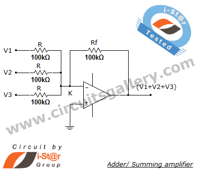
Description: A summing amplifier, also known as an adder, is utilized to combine two or more signal voltages. This voltage adder circuit is straightforward and allows for the addition of multiple signals. It has a wide range of applications in electronic circuits. For instance, in a precision amplifier, it may be necessary to add a small voltage to correct the offset error of the operational amplifier itself. An audio mixer serves as another example of combining waveforms (such as vocals and instruments) from different channels before sending the mixed signal to a recorder. The circuit allows for gain adjustments or the addition of extra inputs without affecting the gains of other inputs. It is important to note that the inverting summing amplifier circuit inverts the input signals. If the opposite polarity is required, an inverting stage can be added either before or after the summing stage.
A summing amplifier circuit typically employs operational amplifiers (op-amps) configured to perform arithmetic addition of input voltages. The most common configuration is the inverting summing amplifier, where multiple input signals are fed into the inverting terminal of the op-amp through resistors. The non-inverting terminal is connected to ground. The output voltage is a weighted sum of the input voltages, with each input signal scaled by its corresponding resistor value. The relationship between the input voltages (V1, V2,..., Vn) and the output voltage (Vout) can be expressed by the formula:
Vout = - (R_f / R1 * V1 + R_f / R2 * V2 + ... + R_f / Rn * Vn)
where R_f is the feedback resistor and R1, R2, ..., Rn are the resistors connected to the inputs.
This configuration allows for flexibility in signal processing, making it suitable for applications such as audio mixing, where signals from various sources need to be combined while maintaining control over individual signal levels. The ability to adjust the gain for each input independently is achieved by selecting appropriate resistor values.
In cases where non-inverted output is required, a non-inverting summing amplifier can be implemented. This can be done by using a second op-amp stage that follows the inverting summing amplifier. The second stage can be configured to provide the desired gain and phase characteristics, allowing for greater versatility in circuit design.
Overall, summing amplifiers are essential components in various electronic applications, providing a means to combine multiple signals effectively while maintaining control over the output characteristics.Summing amplifier or an adder is used to sum two signal voltages. Voltage adder circuit is a simple circuit that enables you to add several signals together. It has wide variety of applications in electronic circuits. For example, on a precision amplifier, you may need to add a small voltage to cancel the offset error of the op amp itself. An audi o mixer is another good example of adding waveforms (sounds) together from different channels (vocals, instruments) before sending the combined signal to a recorder. You can change the gain or add another input without messing up with the gains of other inputs. Just remember that the inverting summing amplifier circuit inverts the input signals. That`s not a big deal. If you need the opposite polarity, all you have to do is to put an inverting stage before or after the summer.
A summing amplifier circuit typically employs operational amplifiers (op-amps) configured to perform arithmetic addition of input voltages. The most common configuration is the inverting summing amplifier, where multiple input signals are fed into the inverting terminal of the op-amp through resistors. The non-inverting terminal is connected to ground. The output voltage is a weighted sum of the input voltages, with each input signal scaled by its corresponding resistor value. The relationship between the input voltages (V1, V2,..., Vn) and the output voltage (Vout) can be expressed by the formula:
Vout = - (R_f / R1 * V1 + R_f / R2 * V2 + ... + R_f / Rn * Vn)
where R_f is the feedback resistor and R1, R2, ..., Rn are the resistors connected to the inputs.
This configuration allows for flexibility in signal processing, making it suitable for applications such as audio mixing, where signals from various sources need to be combined while maintaining control over individual signal levels. The ability to adjust the gain for each input independently is achieved by selecting appropriate resistor values.
In cases where non-inverted output is required, a non-inverting summing amplifier can be implemented. This can be done by using a second op-amp stage that follows the inverting summing amplifier. The second stage can be configured to provide the desired gain and phase characteristics, allowing for greater versatility in circuit design.
Overall, summing amplifiers are essential components in various electronic applications, providing a means to combine multiple signals effectively while maintaining control over the output characteristics.Summing amplifier or an adder is used to sum two signal voltages. Voltage adder circuit is a simple circuit that enables you to add several signals together. It has wide variety of applications in electronic circuits. For example, on a precision amplifier, you may need to add a small voltage to cancel the offset error of the op amp itself. An audi o mixer is another good example of adding waveforms (sounds) together from different channels (vocals, instruments) before sending the combined signal to a recorder. You can change the gain or add another input without messing up with the gains of other inputs. Just remember that the inverting summing amplifier circuit inverts the input signals. That`s not a big deal. If you need the opposite polarity, all you have to do is to put an inverting stage before or after the summer.
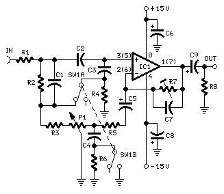
Auto Loudness Control
Simple add-on module. A simple approach to this problem can be done inserting a circuit in the preamplifier stage, capable of varying automatically the frequency response of the entire audio chain in respect to the position of the control knob,...
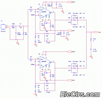
LM3886 100W Power Audio Amplifier circuit
The following circuit diagram depicts a 100 Watt audio power amplifier, constructed using the LM3886 power amplifier chip. A single LM3886 IC can amplify audio power output up to 68W. In this circuit, two LM3886 chips are configured in parallel.
The...
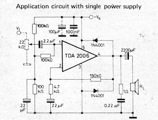
Small IC amplifiers for speakers
A small amplifier IC circuit has been compiled. This circuit is part of an older series and is categorized as a simple OTL (Output Transformer-Less) circuit.
The presented small amplifier IC circuit is designed for applications where compact size and simplicity...
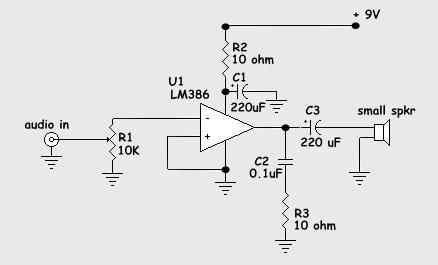
Build A Simple Twin Tee Phase Shift Audio Oscillator and Audio Amplifier
The schematic diagram presented is of a twin "T" phase shift oscillator, an audio oscillator. This oscillator derives its name from the phase shift network formed by resistors R3, R4, and capacitors C1, C2, and C3. This network shifts the...
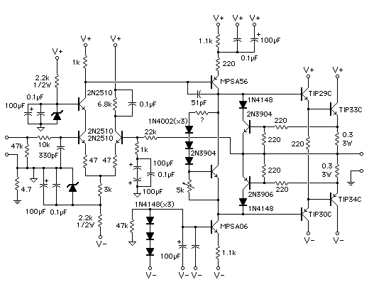
Audio Power Amplifier
Measure the voltage across the 1k resistor connected to the input stage and Vcc. The DC voltage should be approximately 2 volts, or 2 mA of current flowing through this resistor. For instance, if Vcc is at 24 volts, the...
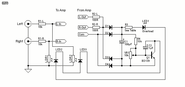
Audio Power Limiter
The gain control element is a Light Dependent Resistor (LDR). These are blessed with a few very useful features for our purposes, one of which is low distortion even at quite high signal levels. Being light activated, all we need...
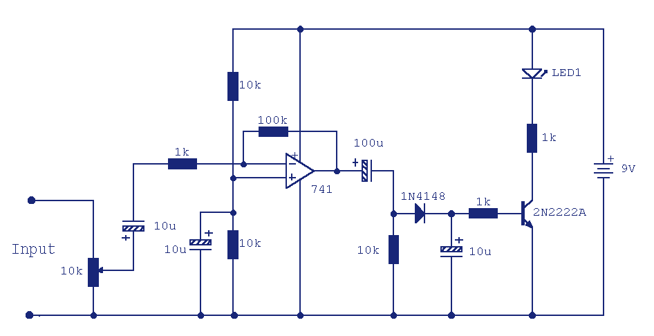
Audio peak Indicator
This circuit can be used to remotely monitor a loudspeaker, alarm, or audio source for presence of an audio waveform. It can also be directly connected across loudspeaker terminals used as a peak indicator. If you need to monitor some...
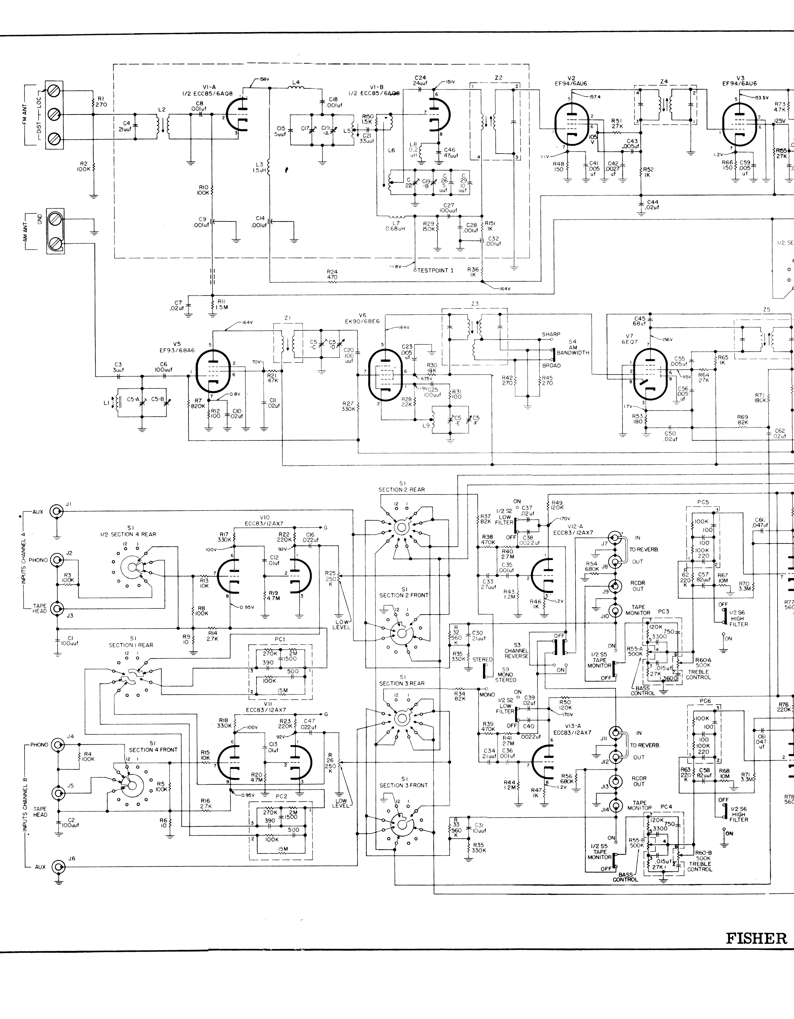
DIY Fisher 800b into a mic pre
A Fisher 800B hi-fi amplifier in excellent condition is intended for conversion into a microphone preamplifier. The power supply's silicon diodes require replacement with modern, low-noise alternatives. All electrolytic capacitors also need replacing, while the signal capacitors may still be...
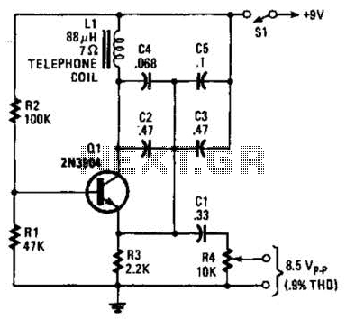
Simple Audio Test Oscillator Circuit
An 88 mH surplus telephone toroidal coil is utilized in a 1 kHz oscillator. It can provide up to 8 V peak-to-peak into a high-impedance load. The total harmonic distortion (THD) is 0.9%.
The circuit employs an 88 mH toroidal coil,...