


TWO QUADRANT
#digital multiplier
#DAC-08
#OP-02
#precision
#offset-binary
#analog circuit
#signal processing
#bipolar output
#monolithic
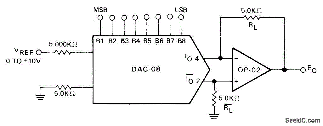
Description: A bipolar digital multiplier has its output polarity controlled by an offset binary-coded digital input word. The Precision Monolithics DAC-08 digital-to-analog converter drives the OP-02 operational amplifier. The output is symmetrical about the ground.
The described circuit employs a bipolar digital multiplier that utilizes an offset binary-coded digital input to control the output polarity. This configuration allows for precise manipulation of the output signal, which is particularly useful in applications requiring accurate signal processing and conversion.
The core component of this circuit is the Precision Monolithics DAC-08, a highly regarded digital-to-analog converter known for its precision and reliability. The DAC-08 converts the digital input signal into an analog output, which is then processed by the OP-02 operational amplifier. The OP-02 is selected for its low noise and high-performance characteristics, enhancing the overall fidelity of the output signal.
The output of the circuit is designed to be symmetrical about the ground, meaning that it can produce both positive and negative voltage swings relative to the ground reference. This feature is essential in various signal processing applications, as it allows for the representation of bipolar signals, which are common in many electronic systems.
In summary, this bipolar digital multiplier circuit effectively translates digital inputs into precise analog outputs while maintaining symmetry about the ground, making it suitable for a wide range of applications in electronic signal processing. The combination of the DAC-08 and the OP-02 op-amp ensures high performance and accuracy in the generated output signals.Bipolar digital multiplier has output polarity controlled by offset-binary-coded digital input word. Precision Monolithics DAC-08 D/A converter drives OP-02 opamp. 0utput is symmetrical about ground. -J. Schoeff and D. Soderquist, Differential and Multiplying Digital to Analog Converter Applications, Precision Monolithics, Santa Clara, CA, 1976, AN -19, p2.
The described circuit employs a bipolar digital multiplier that utilizes an offset binary-coded digital input to control the output polarity. This configuration allows for precise manipulation of the output signal, which is particularly useful in applications requiring accurate signal processing and conversion.
The core component of this circuit is the Precision Monolithics DAC-08, a highly regarded digital-to-analog converter known for its precision and reliability. The DAC-08 converts the digital input signal into an analog output, which is then processed by the OP-02 operational amplifier. The OP-02 is selected for its low noise and high-performance characteristics, enhancing the overall fidelity of the output signal.
The output of the circuit is designed to be symmetrical about the ground, meaning that it can produce both positive and negative voltage swings relative to the ground reference. This feature is essential in various signal processing applications, as it allows for the representation of bipolar signals, which are common in many electronic systems.
In summary, this bipolar digital multiplier circuit effectively translates digital inputs into precise analog outputs while maintaining symmetry about the ground, making it suitable for a wide range of applications in electronic signal processing. The combination of the DAC-08 and the OP-02 op-amp ensures high performance and accuracy in the generated output signals.Bipolar digital multiplier has output polarity controlled by offset-binary-coded digital input word. Precision Monolithics DAC-08 D/A converter drives OP-02 opamp. 0utput is symmetrical about ground. -J. Schoeff and D. Soderquist, Differential and Multiplying Digital to Analog Converter Applications, Precision Monolithics, Santa Clara, CA, 1976, AN -19, p2.
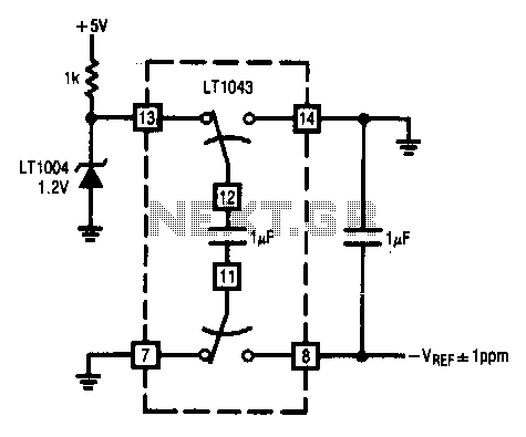
Precision-voltage-inverter
This circuit enables the inversion of a reference signal with an accuracy of 1 ppm. It features high input impedance and does not require any trimming.
The described circuit is designed to invert a reference voltage signal while maintaining a high...
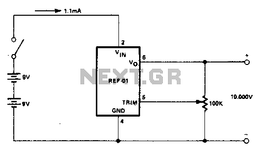
Precision calibration standard
An external power supply that provides a voltage higher than the maximum expected rating of the zener diodes to be tested is required. Potentiometer RV1 is adjusted until the meter reading stabilizes. This reading represents the breakdown voltage of the...
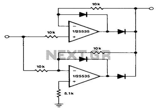
Precision-full-wave-rectifier
This circuit provides accurate full-wave rectification. The output impedance is low for both input polarities, and the errors are small at all signal levels. It is important to note that the output will not sink heavy currents, except for a...
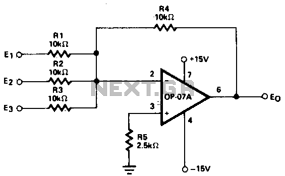
Adjustment-free precision summing amplifier
This circuit generates continuous outputs that depend on multiple input variables.
The circuit in question typically employs a combination of operational amplifiers (op-amps), resistors, and potentiometers to achieve its functionality. The outputs can be tailored based on the variations in...
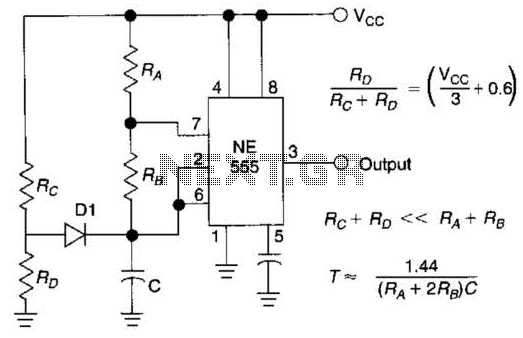
Precision Lf Oscillator Circuit
Using Rl, R7, and D1 to preset CI to one third of the supply voltage. This circuit avoids a longer first cycle period than subsequent cycles.
The circuit described involves the use of resistors Rl and R7 along with diode D1...
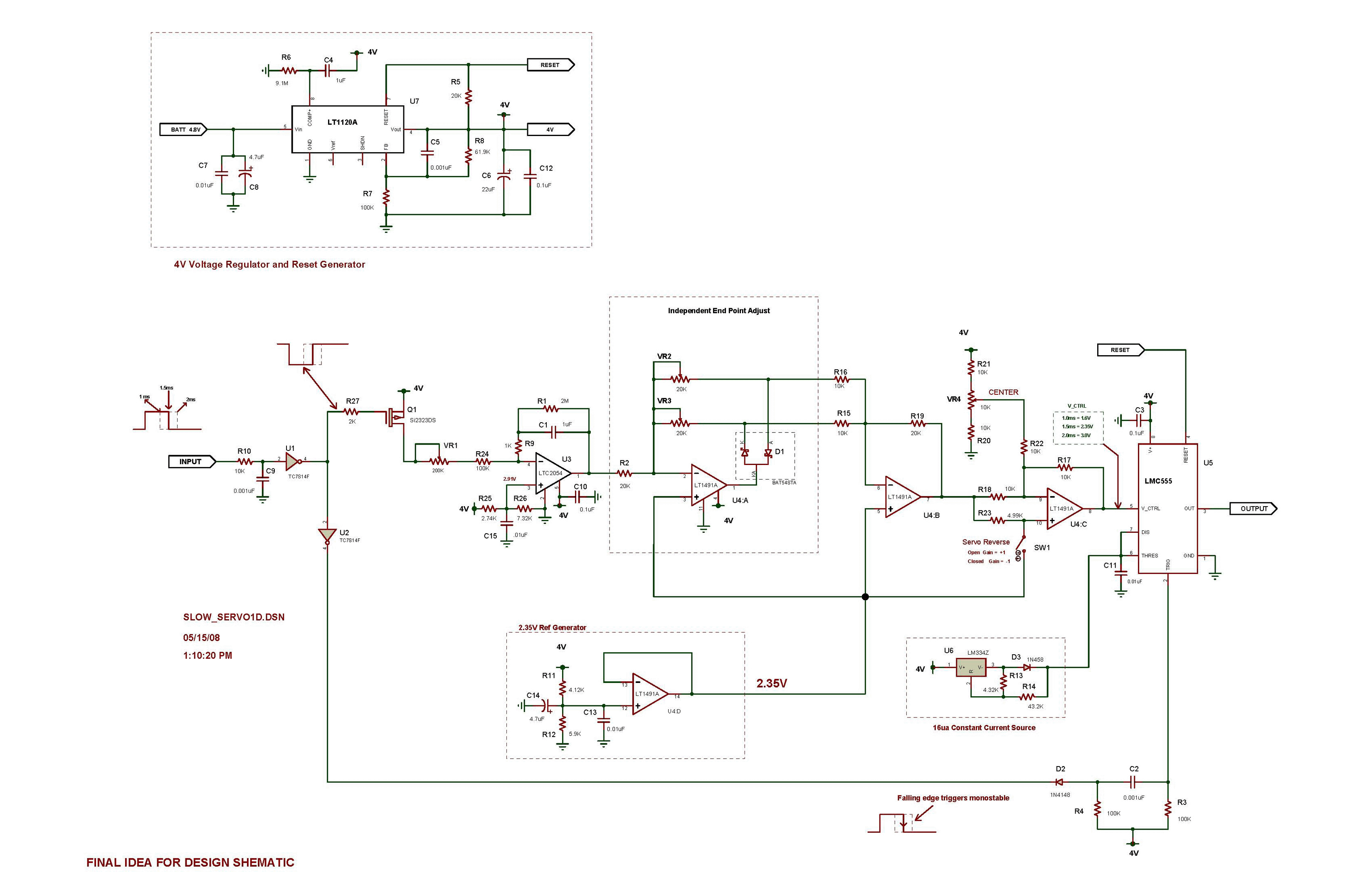
Analog circuit enforces slow servo response
The all-analog circuit presented controls the rate at which a miniature turbojet engine can be throttled. Increasing or decreasing the throttle too quickly on a miniature turbojet engine, or any jet engine, can lead to quick failure in flight, causing...
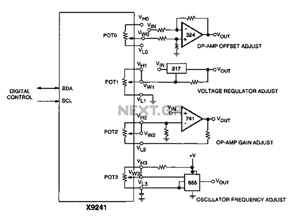
Corrector circuit diagram of an analog circuit
A XICOR X9241 POT IC module can be utilized to modify the four digital analog circuits, as depicted in the schematic.
The XICOR X9241 is a digital potentiometer integrated circuit designed for precise adjustment of analog signal levels in various electronic...
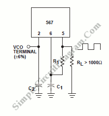
Precision Oscillator With 20ns Switching
A precision oscillator can be constructed using a quartz crystal; however, with appropriate component selection, it is also possible to build one using an RC (resistor and capacitor) circuit.
An RC oscillator generates an oscillating signal through the use of resistors...
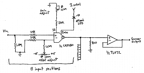
Interpolating Scanner Circuit
This design is for an interpolating scanner, a circuit featuring multiple signal inputs, a control voltage input, and a signal output. The output selectively transitions between inputs, smoothly fading from one to the next as the control voltage increases. A...