


Universal Compander
#compander
#NE575
#audio processing
#signal compression
#signal expansion
#battery power
#low voltage
#Signetics
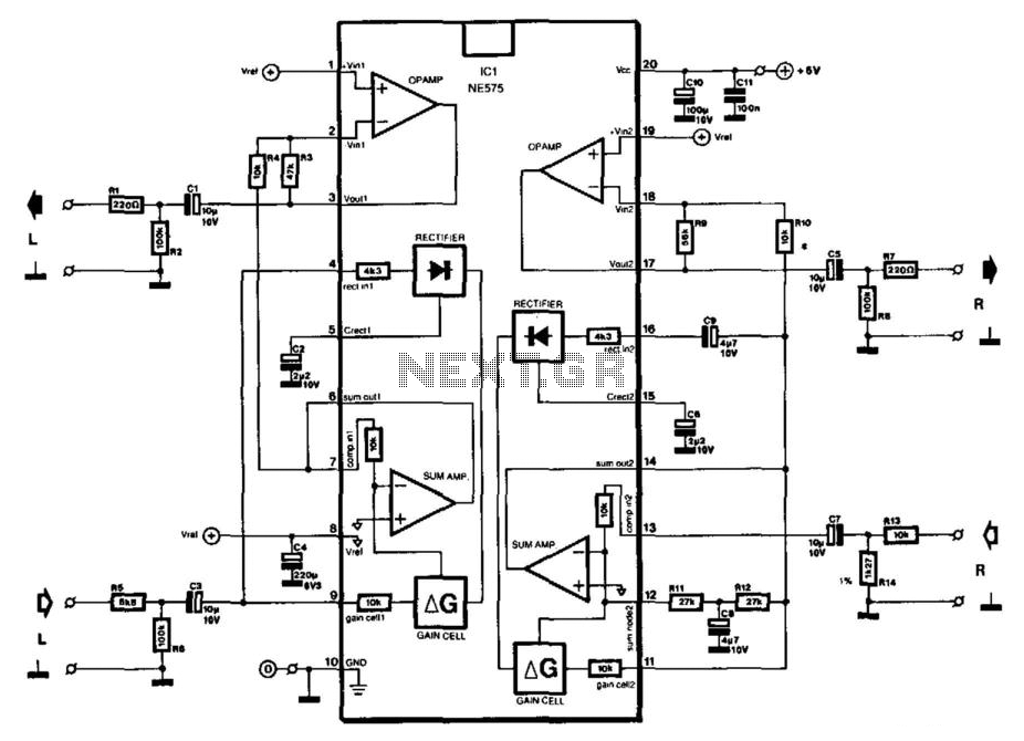
Description: The NE575 compander IC by Signetics is designed primarily for use with battery power supplies ranging from 3 to 7 V (maximum 8 V). It consumes a current of 3.5 mA at 3 V and 5 mA at 7 V. The compander process, which involves compression at the input and expansion at the output, significantly enhances the signal-to-noise ratio in a communications link. The IC consists of two nearly identical circuits; one (pins 1 to 9) functions as an expander, while the other (pins 11 to 19) can serve as an expander, compressor, or automatic load control (ALC), depending on the external circuitry connected. For the compressor function, the inverting output of the internal summing amplifier is accessible at pin 12, which is not available in the expander section, where a reference voltage is provided at pin 8. This pin is interconnected with pins 1 and 19 to facilitate the setting of the DC operating point of the operational amplifiers. The operational amplifier in the expander section (pins 1 through 3) acts as an output buffer, while pins 17 through 19 serve as the input buffer in the compressor section. The IC exhibits relatively high output sensitivity, indicating it is intended for processing small signals, such as microphone output levels. For example, a 100 mV signal is amplified by only 1. The current circuit is designed to handle larger input signals (line level), with a maximum input level of 1.5 Vrms. With a 1-V input into R13, a potential of approximately 500 mV exists between the compressor output (R7) and the expander input (R5). The compression characteristic is illustrated in Fig. 19-2 (b), where the signal range is reduced by about half at the output, which is then doubled in the expander. Consequently, the range after compression and expansion returns to its original state, although this does not guarantee equivalent input and output levels. The compander can be configured to provide either constant attenuation or amplification. With the circuit values indicated in the diagram, the input and output levels remain the same. The prototype demonstrated an overall gain of 0.5 dB when the expander input was directly connected to the compressor output. To accommodate high input levels, R13, R14, and the compressor input resistance create a 10:1 attenuator. At the expander input, R5 and the expander input impedance of approximately 3 kΩ form a potential divider. If the compander is intended for use with smaller signals, the attenuation can be adjusted accordingly. For input levels below 100 mV, R5, R13, and R14 can be omitted. The compander operates across a frequency range of 20 Hz to 20 kHz, with overall distortion below 1% and a signal-to-noise ratio of about 80 dB.
The NE575 compander IC is a versatile component suitable for various audio processing applications. Its dual-functionality allows for both compression and expansion of audio signals, making it ideal for improving the clarity and quality of audio communications. The design emphasizes low power consumption, making it suitable for battery-operated devices. The ability to adjust the circuit for different input levels enhances its adaptability for various use cases, from professional audio equipment to consumer electronics.
In practical applications, the NE575 can be integrated into systems requiring dynamic range control, such as in wireless microphones, telecommunication devices, and sound reinforcement systems. The internal architecture of the IC facilitates efficient signal processing, ensuring minimal distortion and high fidelity of the audio signal. By employing external resistors and capacitors, users can fine-tune the performance characteristics of the compander to meet specific requirements for signal processing, thus providing flexibility in design and implementation.
Overall, the NE575 compander IC represents a robust solution for enhancing audio signal quality while maintaining low power consumption, making it a valuable component in modern electronic designs. Signetics" type NE575 compander IC is intended primarily for use with battery power supplies of 3 to 7 V (max. 8 V). It draws a current of 3.5 mA at 3 V and 5 mA at 7 V. The compander process (compression at the input, expansion at the output) significantly improves the signal-to-noise ratio in a communications link. The IC contains two almost identical circuits, of which one (pins 1 to 9) is arranged as an expander.
The other (pins 11 to 19) can be used as expander, compressor or automatic load control (ALC), depending on the externally connected circuit. For the compressor function, the inverting output of the internal summing amplifier is brought out to pin 12.
This is not the case in the expander section, where a reference voltage is available at pin 8. This pin is interlinked to pins 1 and 19 to enable the setting of the dc operating point of the op amps. The op amp in the expander section, pins 1 through 3, serves as output buffer in the compressor section, pins 17 through 19 as the input buffer.
The IC has a relatively high output sensitivity and is evidently intended for processing small signals (microphone output level). A signal of 100 mV, for instance, is amplified by 1 only. The present circuit caters to larger input signals (line level); its maximum input level is 1.5 Vrms.
With a 1-V input into R13, a potential of about 500 mV exists between compressor output R7 and expander input R5. The compression characteristic is shown in Fig. 19-2 (b). The signal range is reduced by about one half at the output, which is doubled in the expander. Thus, the range after compression and expansion is the same again, but that is not necessarily the case with the input and output level.
The compander can be arranged to provide a constant attenuation or amplification. With the circuit values as shown in the diagram, the input and output levels are the same. The prototype had an overall gain of 0.5 dB when the expander input was connected directly to the compressor output. To allow acceptance of high input levels, R13, R14, and the compressor input resistance form a 10:1 attenuator.
At the expander input, R5 and the expander input impedance of about 3 kfl form a potential divider. If the compander is to be used with smaller signals, the attenuation can be reduced as appropriate. If the input level lies below 100 mV, R5, R13 and R14 can be omitted. The compander covers the frequency range of 20 Hz to 20 kHz, the overall distortion is less than 1%, and the signal-to-noise ratio is about 80 dB.
The NE575 compander IC is a versatile component suitable for various audio processing applications. Its dual-functionality allows for both compression and expansion of audio signals, making it ideal for improving the clarity and quality of audio communications. The design emphasizes low power consumption, making it suitable for battery-operated devices. The ability to adjust the circuit for different input levels enhances its adaptability for various use cases, from professional audio equipment to consumer electronics.
In practical applications, the NE575 can be integrated into systems requiring dynamic range control, such as in wireless microphones, telecommunication devices, and sound reinforcement systems. The internal architecture of the IC facilitates efficient signal processing, ensuring minimal distortion and high fidelity of the audio signal. By employing external resistors and capacitors, users can fine-tune the performance characteristics of the compander to meet specific requirements for signal processing, thus providing flexibility in design and implementation.
Overall, the NE575 compander IC represents a robust solution for enhancing audio signal quality while maintaining low power consumption, making it a valuable component in modern electronic designs. Signetics" type NE575 compander IC is intended primarily for use with battery power supplies of 3 to 7 V (max. 8 V). It draws a current of 3.5 mA at 3 V and 5 mA at 7 V. The compander process (compression at the input, expansion at the output) significantly improves the signal-to-noise ratio in a communications link. The IC contains two almost identical circuits, of which one (pins 1 to 9) is arranged as an expander.
The other (pins 11 to 19) can be used as expander, compressor or automatic load control (ALC), depending on the externally connected circuit. For the compressor function, the inverting output of the internal summing amplifier is brought out to pin 12.
This is not the case in the expander section, where a reference voltage is available at pin 8. This pin is interlinked to pins 1 and 19 to enable the setting of the dc operating point of the op amps. The op amp in the expander section, pins 1 through 3, serves as output buffer in the compressor section, pins 17 through 19 as the input buffer.
The IC has a relatively high output sensitivity and is evidently intended for processing small signals (microphone output level). A signal of 100 mV, for instance, is amplified by 1 only. The present circuit caters to larger input signals (line level); its maximum input level is 1.5 Vrms.
With a 1-V input into R13, a potential of about 500 mV exists between compressor output R7 and expander input R5. The compression characteristic is shown in Fig. 19-2 (b). The signal range is reduced by about one half at the output, which is doubled in the expander. Thus, the range after compression and expansion is the same again, but that is not necessarily the case with the input and output level.
The compander can be arranged to provide a constant attenuation or amplification. With the circuit values as shown in the diagram, the input and output levels are the same. The prototype had an overall gain of 0.5 dB when the expander input was connected directly to the compressor output. To allow acceptance of high input levels, R13, R14, and the compressor input resistance form a 10:1 attenuator.
At the expander input, R5 and the expander input impedance of about 3 kfl form a potential divider. If the compander is to be used with smaller signals, the attenuation can be reduced as appropriate. If the input level lies below 100 mV, R5, R13 and R14 can be omitted. The compander covers the frequency range of 20 Hz to 20 kHz, the overall distortion is less than 1%, and the signal-to-noise ratio is about 80 dB.
Audio Beat Detect ?« Electronic Product Design
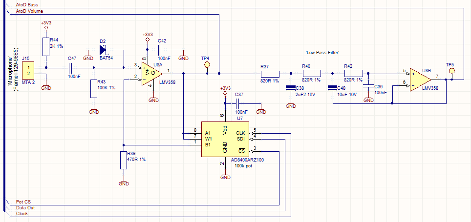
This circuit employs a digital potentiometer to enable the microcontroller to automatically adjust the circuit's gain according to the ambient audio volume. However, a standard potentiometer can be used if automatic adjustment is unnecessary. The low-pass filter design is based...
Simple low voltage Oscillator circuit
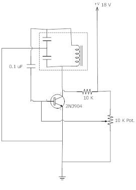
The frequency remains stable as the voltage decreases. It is referred to as the "backwards JT" because it operates optimally with a bifilar coil and a single transistor. With a modification to the circuit, it is possible to deplete a...
Low voltage flasher
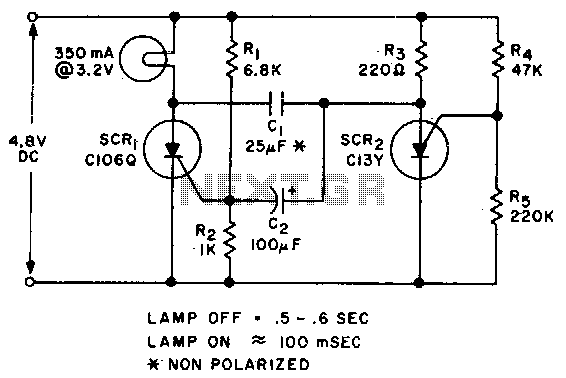
Applying voltage to the circuit triggers SCR1. With SCR1 on, the voltage on the anode of SCR2 rises until SCR2 triggers to commutate SCR1. The voltage on the gate of SCR1 will swing negative at this time, and only after...
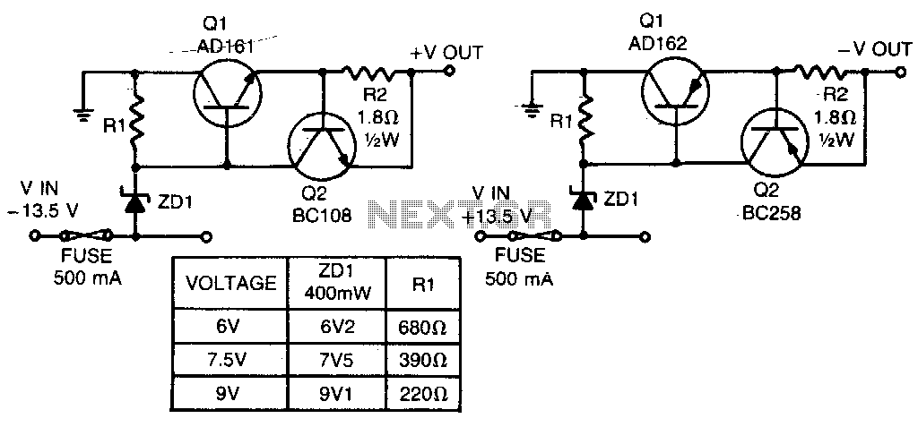
Low voltage regulators
These short-circuit protected regulators provide output voltages of 6, 7, and 9 V from a nominal automobile battery supply of 13 V. They are also compatible with smoothed DC outputs from transformer/rectifier circuits. Two configurations are designed for both positive...
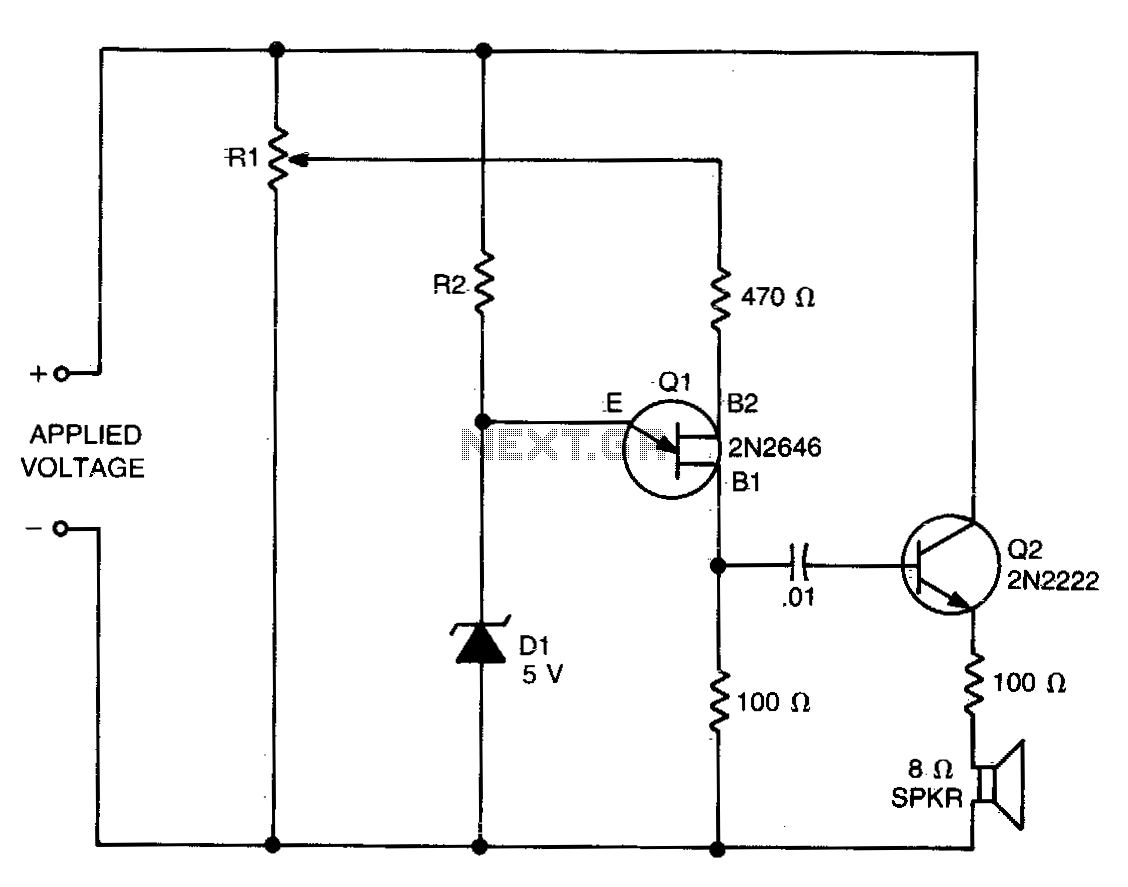
Low voltage detector
The values of R1, R2, and D1 are selected based on the voltage applied. Using a 12-volt battery, R1 is set to 10 kΩ, R2 to 5 kΩ, and D1 is a 5-volt zener diode or a string of forward-biased...
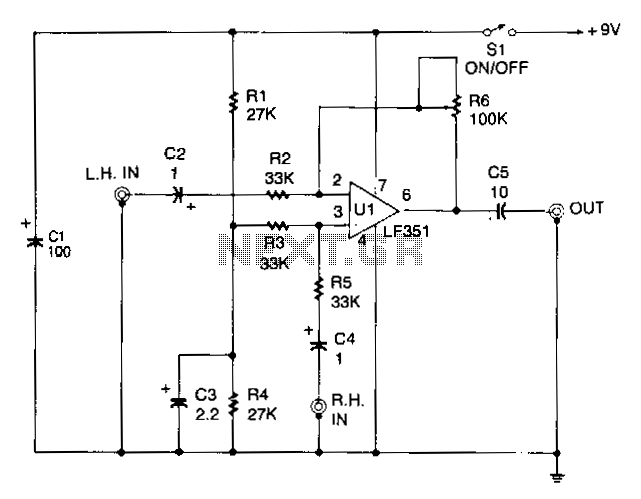
Central-image-canceller
The circuit is designed to eliminate the vocal portion of an audio signal while preserving the instrumental portion. It achieves this by mixing two channels that are 180° out of phase, allowing the signals that create the center-stereo image to...
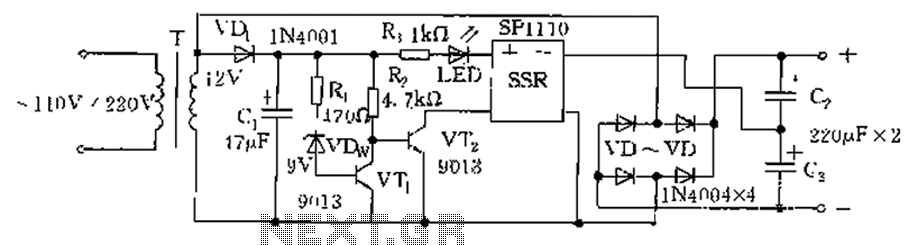
Schematic circuit diagram of low voltage and low voltage automatic conversion
The circuit is automatically converted to a low-voltage configuration. A 220V AC supply is stepped down by transformer T. After this, the breakdown voltage of diode VDw causes transistors VT1 and VT2 to turn off, resulting in the solid-state relay...
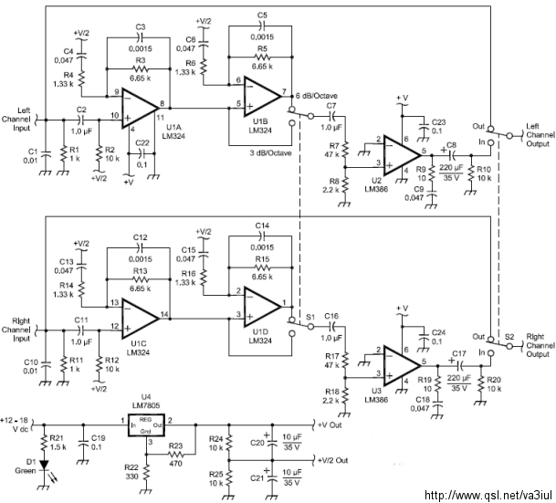
ARRL Handbook Audio Intelligibility Enhancer
Assistance is sought for building the N4GG audio intelligibility enhancer project as detailed in the ARRL Handbook. A circuit board has been ordered from Far Circuits, but there are difficulties in sourcing the necessary components. Attempts have been made to...
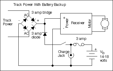
Battery Powered Radio Control Tips
The primary motivation for utilizing battery power for trains is to eliminate the need for track cleaning and wiring. Track maintenance can pose significant challenges. Incorporating radio control into a battery-powered system enhances command control, an advantageous feature. In certain...