


Video Fader Circuit
#video signal
#fader
#composite signal
#synchronization
#attenuation
#signal processing
#video processing
#electronics
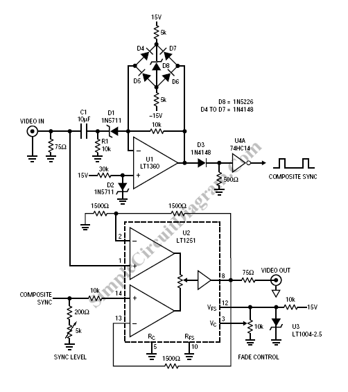
Description: Fading a video signal cannot be achieved merely by attenuating the composite signal, as the synchronization signal may fall below an unacceptable level.
Fading a video signal involves a careful adjustment of both the luminance and chrominance components while maintaining the integrity of the synchronization signals. Simply reducing the amplitude of the composite video signal can lead to a situation where the sync pulses become too weak, causing potential issues in the display of the video.
To implement a proper fading circuit, a more sophisticated approach is required. This can be accomplished using a dedicated video fading circuit that utilizes operational amplifiers (op-amps) configured to handle the specific frequency ranges of the video signal.
A typical schematic for a video fading circuit would include the following components:
1. **Input Stage**: The composite video signal is fed into the circuit, typically through a BNC connector. This signal carries both the video information and synchronization pulses.
2. **Buffering**: An initial op-amp buffer may be used to isolate the input signal from the fading circuit. This ensures that the loading effect does not alter the signal characteristics.
3. **Attenuation Control**: A variable resistor (potentiometer) can be used to adjust the level of attenuation applied to the signal. This potentiometer should be connected in a voltage divider configuration with feedback to the op-amp to maintain the signal integrity.
4. **Synchronization Preservation**: To ensure that the sync pulses are not adversely affected, a high-pass filter may be employed to separate the sync signals from the video information. This allows for independent control of the sync level, which can be mixed back into the output signal after fading.
5. **Output Stage**: After processing, the faded video signal is then sent to another op-amp configured as a summing amplifier. This stage combines the faded video signal with the adjusted sync pulses before outputting the final composite video signal.
6. **Power Supply Considerations**: The entire circuit should be powered by a stable DC power supply, typically +12V or +15V, to ensure that the op-amps operate within their specified range.
By carefully designing the circuit in this manner, the fading effect can be achieved without compromising the quality of the synchronization signals, ensuring that the video remains stable and viewable throughout the fading process.Fading a video signal can`t be done simply by attenuating the composite signal, since the synchronization signal may drop below unacceptable level. Here a..
Fading a video signal involves a careful adjustment of both the luminance and chrominance components while maintaining the integrity of the synchronization signals. Simply reducing the amplitude of the composite video signal can lead to a situation where the sync pulses become too weak, causing potential issues in the display of the video.
To implement a proper fading circuit, a more sophisticated approach is required. This can be accomplished using a dedicated video fading circuit that utilizes operational amplifiers (op-amps) configured to handle the specific frequency ranges of the video signal.
A typical schematic for a video fading circuit would include the following components:
1. **Input Stage**: The composite video signal is fed into the circuit, typically through a BNC connector. This signal carries both the video information and synchronization pulses.
2. **Buffering**: An initial op-amp buffer may be used to isolate the input signal from the fading circuit. This ensures that the loading effect does not alter the signal characteristics.
3. **Attenuation Control**: A variable resistor (potentiometer) can be used to adjust the level of attenuation applied to the signal. This potentiometer should be connected in a voltage divider configuration with feedback to the op-amp to maintain the signal integrity.
4. **Synchronization Preservation**: To ensure that the sync pulses are not adversely affected, a high-pass filter may be employed to separate the sync signals from the video information. This allows for independent control of the sync level, which can be mixed back into the output signal after fading.
5. **Output Stage**: After processing, the faded video signal is then sent to another op-amp configured as a summing amplifier. This stage combines the faded video signal with the adjusted sync pulses before outputting the final composite video signal.
6. **Power Supply Considerations**: The entire circuit should be powered by a stable DC power supply, typically +12V or +15V, to ensure that the op-amps operate within their specified range.
By carefully designing the circuit in this manner, the fading effect can be achieved without compromising the quality of the synchronization signals, ensuring that the video remains stable and viewable throughout the fading process.Fading a video signal can`t be done simply by attenuating the composite signal, since the synchronization signal may drop below unacceptable level. Here a..
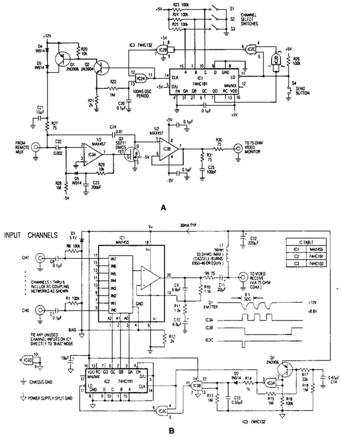
Video Signal Carrier Circuit
In the video system shown in Figs. A and R, a single coaxial cable transmits power to a remote location, selects one of eight video channels, and returns the chosen signal. This system can select from multiple remote surveillance camera...
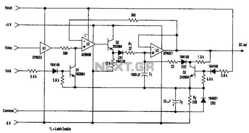
Fast Video Signal Amplitude Measurer Circuit
The amplitude of a video signal can be measured using a straightforward circuit that functions as a modified standard peak detector. This device is capable of verifying RGB signals produced by video RAMDACs. U1 is a high-speed buffer, while U2...
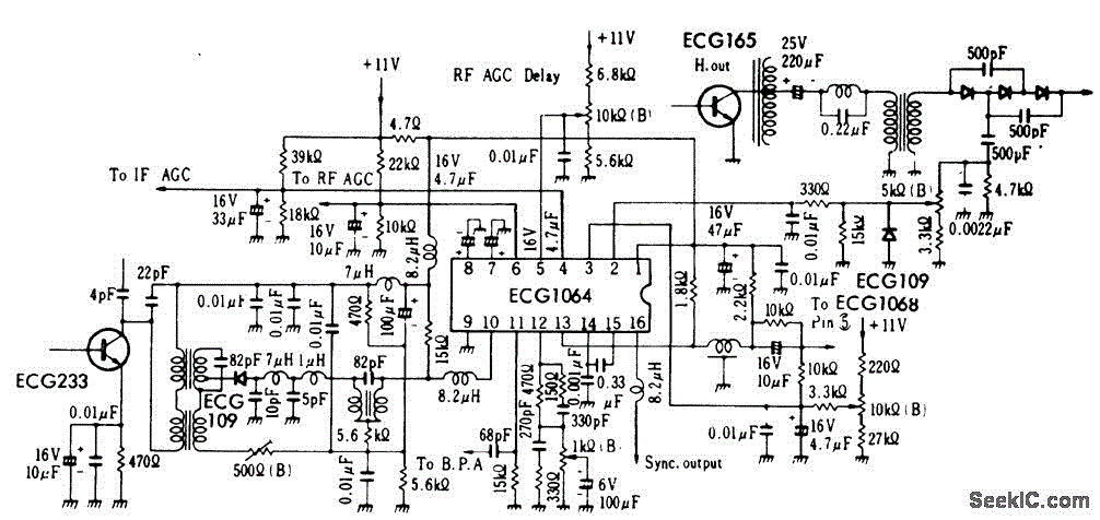
TV_video_signal_processor_circuit_1
TV video signal processor circuit. The ECG1064 chip includes a primary video amplifier, two sync pulse amplifiers, a look-out protector, a noise detector, two noise gates, an automatic gain control (AGC) detector, an intermediate frequency (IF) AGC amplifier, a base...
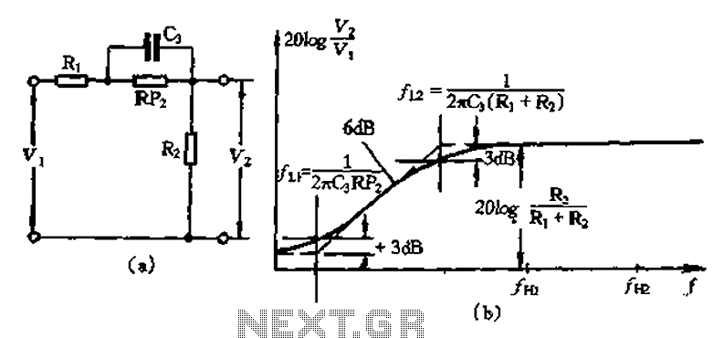
Simplified circuit bass attenuation
There are two corner frequencies present: the start frequency attenuation transition is defined by several parameters, including F1/27rC3 (Ri + R2). This is followed by a decay into a flat corner frequency, denoted as LI, which is represented by l/2rTC3....
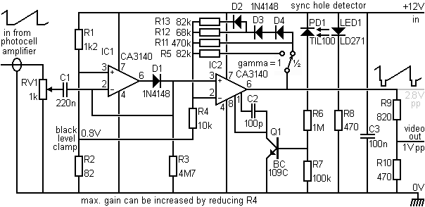
Adding sync pulses to the video signal
This section provides details for generating a composite video output signal from a camera to drive an external monitor. The circuit, designed by Peter Smith, integrates a DC-restorer, a switchable gamma corrector, and a video/sync mixer using a photodiode and...
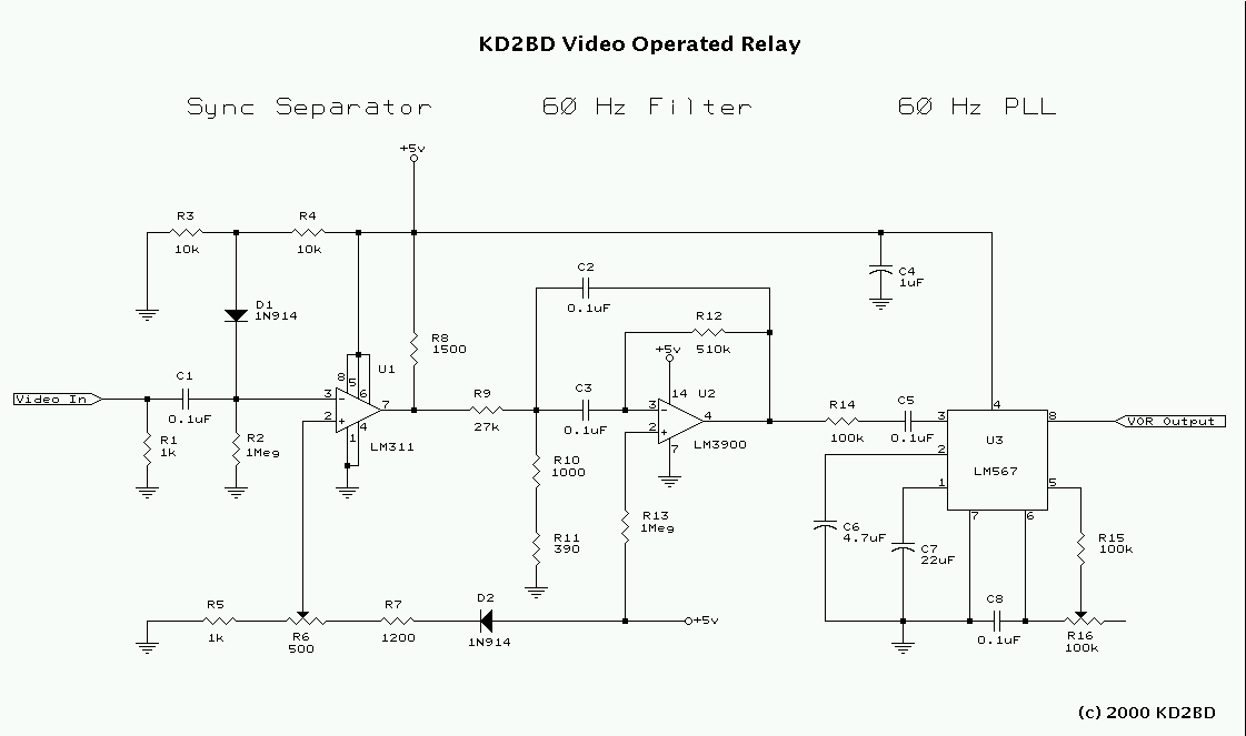
Video Operated Relay
Many Video Operated Relay (VOR) circuits have been published in recent years for use in connection with ATV repeater controllers or automatic videotape logging systems. Unfortunately, many of these circuits fail to properly detect certain video signals depending on their...
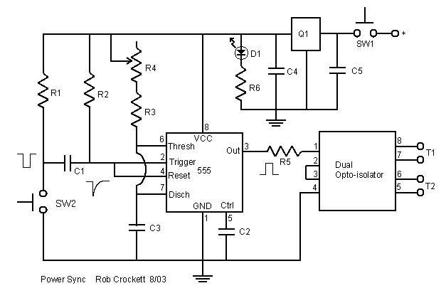
Stereo Digital Camera Power-up Pulse Generator
Powering up twin digital Sony DSC-V1 cameras simultaneously can achieve remarkable synchronization within milliseconds. This is accomplished through the use of dual Sony wired remotes that short the ACC port LANC signal conductor to the ACC port ground. Further experimentation...
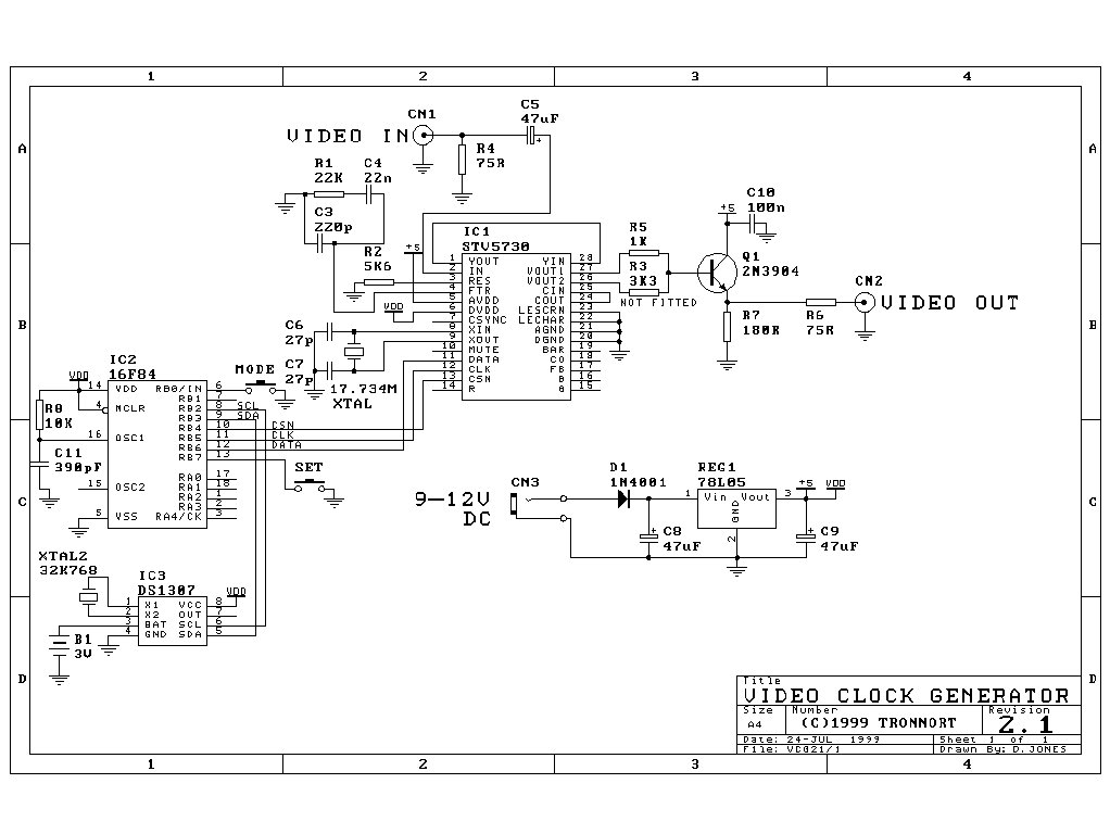
Video Clock and Message Generator
This circuit allows for the superimposition of a title and/or the time and date on an incoming video signal, which is particularly useful when editing video tapes. With the advent of affordable CCD camera modules, setting up a personal video...
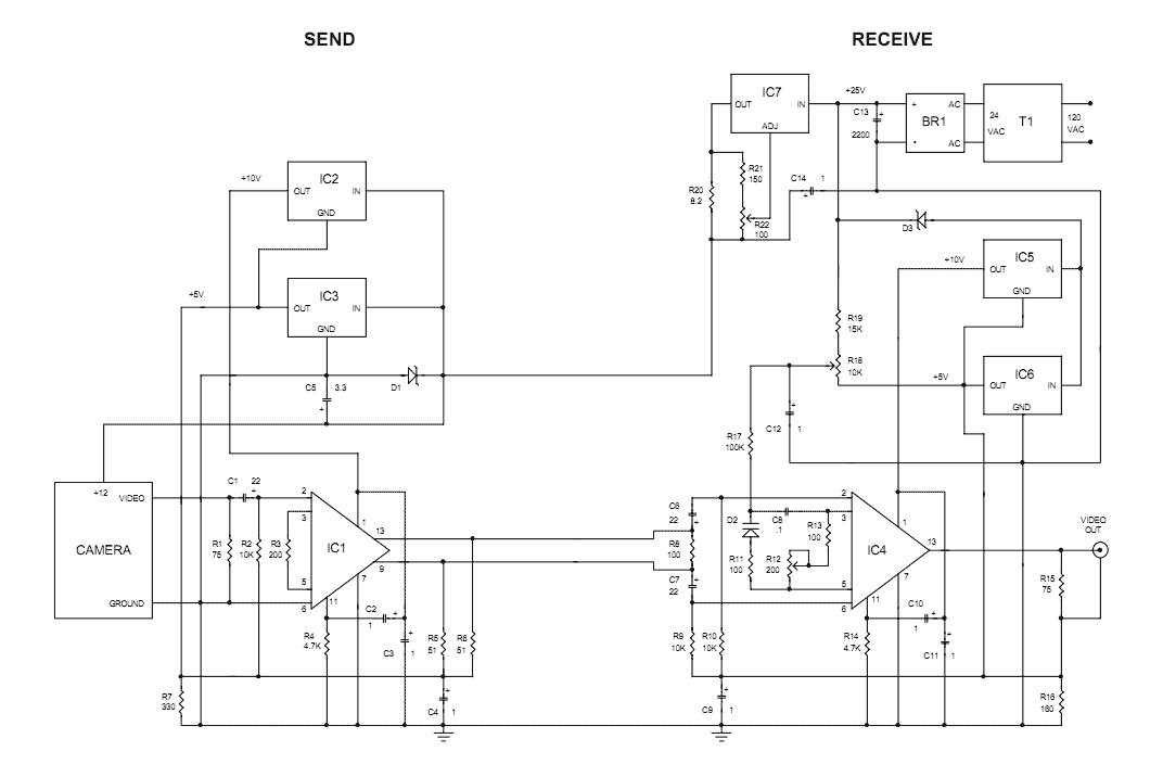
video on telephone line wires
The Videowire converts a baseband video signal into a low impedance differential signal that can be sent over ordinary four conductor telephone wire. A send board mounted close to the camera generates the differential signal and a receive board near...