


VOLTAGE SHIFTING CIRCUIT DIAGRAM
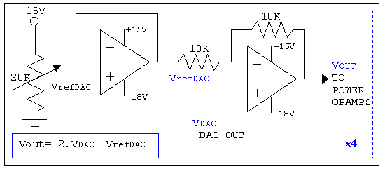
Description: As mentioned in the chapter about the DAC, this circuit shifts the voltage output range. The following diagram explains its operation and structure. The circuit's outputs are connected to the input pins of the power operational amplifiers.
The described circuit is designed to modify the output voltage range of a Digital-to-Analog Converter (DAC). This functionality is crucial in applications where the DAC output needs to be adjusted to fit the input requirements of subsequent stages, such as power operational amplifiers (op-amps). The schematic typically includes the DAC, which generates a voltage based on a digital input signal, and additional components that facilitate the voltage shifting process.
The voltage shifting mechanism may involve operational amplifiers configured in various configurations, such as inverting or non-inverting amplifiers, to achieve the desired gain and offset adjustments. Feedback resistors are commonly used to set the gain, while additional resistors may be employed to create a reference voltage that establishes the output range.
The output from the DAC is fed into the input pins of the power op-amps, which amplify the signal to a level suitable for driving loads or interfacing with other circuit elements. Proper consideration must be given to the power supply requirements of the op-amps to ensure they operate within their specified ranges.
Overall, the circuit's design emphasizes the importance of accurate voltage shifting to ensure compatibility with downstream components, thereby enhancing the overall performance and reliability of the electronic system.As mentioned in the chapter about the DAC, this circuit shifts the voltage output range. The following diagram explains it's operation and structure. The circuits outputs are connected to the input pins of the power opamps.
The described circuit is designed to modify the output voltage range of a Digital-to-Analog Converter (DAC). This functionality is crucial in applications where the DAC output needs to be adjusted to fit the input requirements of subsequent stages, such as power operational amplifiers (op-amps). The schematic typically includes the DAC, which generates a voltage based on a digital input signal, and additional components that facilitate the voltage shifting process.
The voltage shifting mechanism may involve operational amplifiers configured in various configurations, such as inverting or non-inverting amplifiers, to achieve the desired gain and offset adjustments. Feedback resistors are commonly used to set the gain, while additional resistors may be employed to create a reference voltage that establishes the output range.
The output from the DAC is fed into the input pins of the power op-amps, which amplify the signal to a level suitable for driving loads or interfacing with other circuit elements. Proper consideration must be given to the power supply requirements of the op-amps to ensure they operate within their specified ranges.
Overall, the circuit's design emphasizes the importance of accurate voltage shifting to ensure compatibility with downstream components, thereby enhancing the overall performance and reliability of the electronic system.As mentioned in the chapter about the DAC, this circuit shifts the voltage output range. The following diagram explains it's operation and structure. The circuits outputs are connected to the input pins of the power opamps.
Digital To Analog Converter Circuit
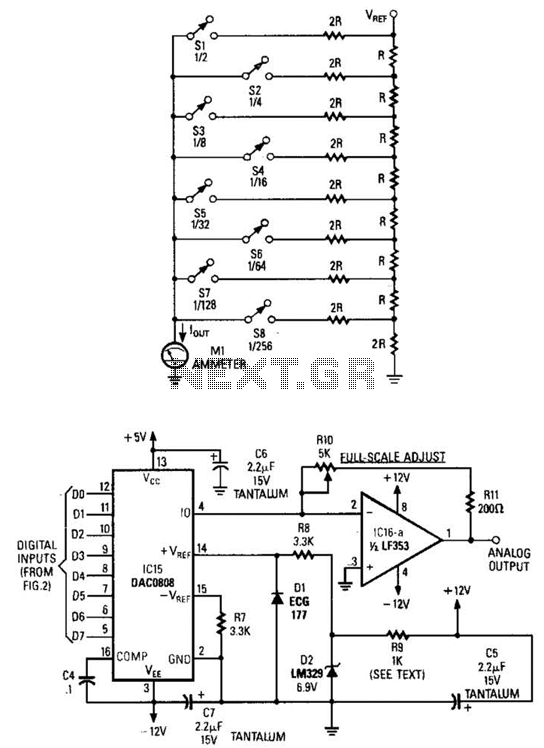
Figure A illustrates an R/2R resistor ladder. Each closed switch increases the current flow. A basic channel A/D converter is depicted in Figure B. The voltage reference (D2) is shared across all channels, although the value of the dropping resistor...
Two 8-bit dacs make a 12-bit dac
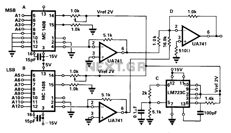
Two MC1408 8-bit D/A converters, designated A and B in the circuit diagram, are utilized. The four least significant bits of A are grounded. The four most significant bits of a 12-bit data input are connected to the remaining four...
8-bit Digital to Analog converter (DAC)
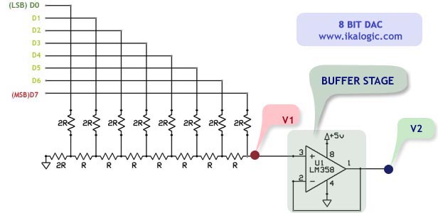
This article introduces a simple solution for beginners and intermediate readers to build a digital-to-analog converter (DAC) using an R/2R resistor network. It also addresses common challenges faced by beginners while constructing their own DACs and offers straightforward solutions. The...
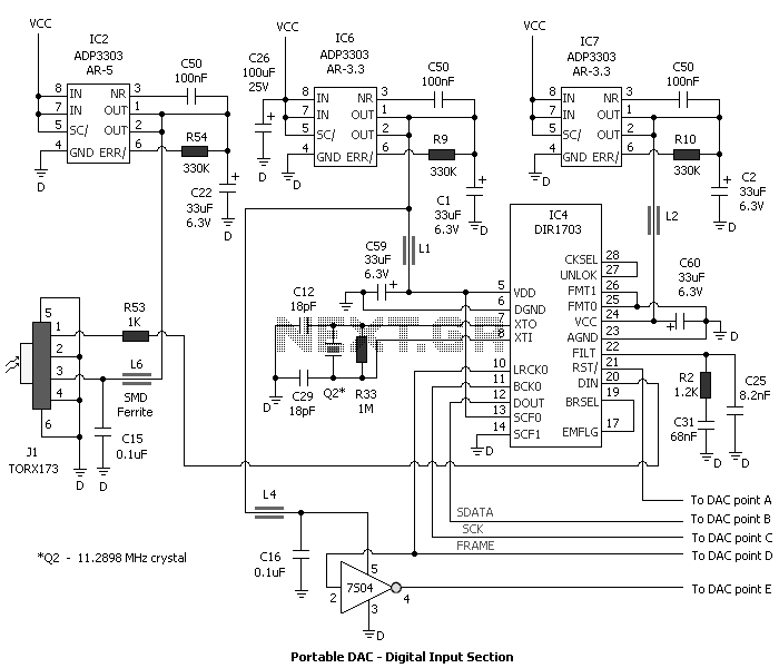
DAC and Headphone Amplifier
The idea behind the portable DAC is to get better sound than from the line out or headphone out of portable CD player, a pc sound card or other digital audio source. Many of us want to listen to music...
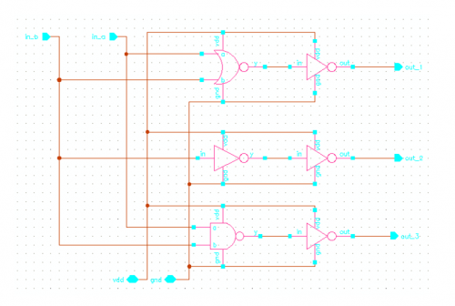
12 bit Digital to Analog Converter
INTRODUCTION Digital to analog converters are one of the most commonly employed circuits in many applications involving digital video, signal processing, and testing.
Digital to analog converters (DACs) serve a critical role in modern electronic systems by converting digital signals, which...
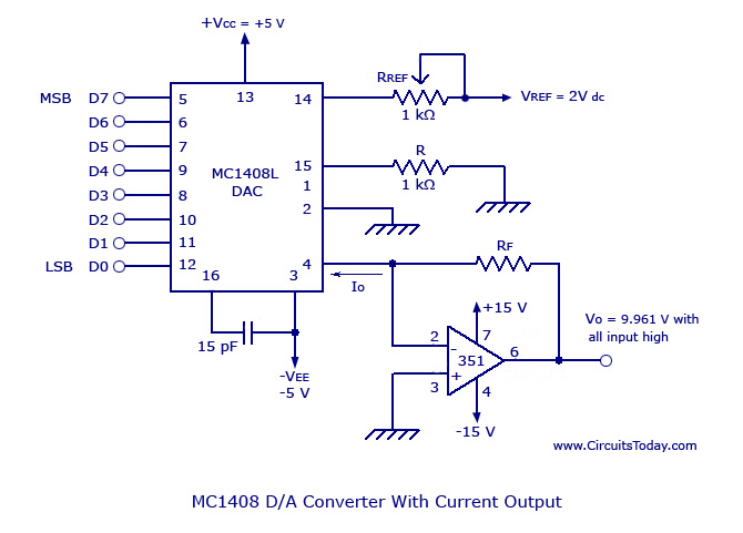
Monolithic/Hybrid Digital to Analog Converters using MC 1408ICSE/NE 5018
Monolithic/Hybrid Digital to Analog Converters using MC 1408 IC, SE/NE 5018, Specifications and Applications.
Monolithic and hybrid digital-to-analog converters (DACs) are integral components in various electronic systems, facilitating the conversion of digital signals into corresponding analog voltages or currents. The MC...
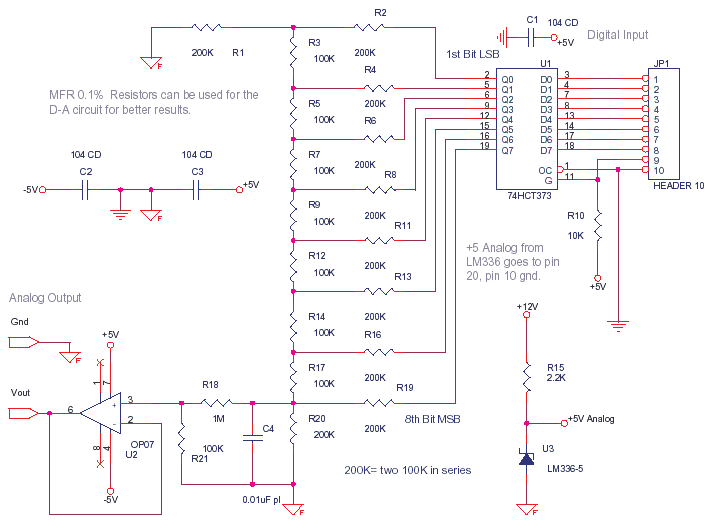
digital to analog
This circuit can be utilized to convert a byte sent from a microcontroller into an analog value, such as 1.51 V. At full scale, when all 8 bits are high, it is calibrated to provide 2.55 V, with each bit...
Digital-to-analog-converters
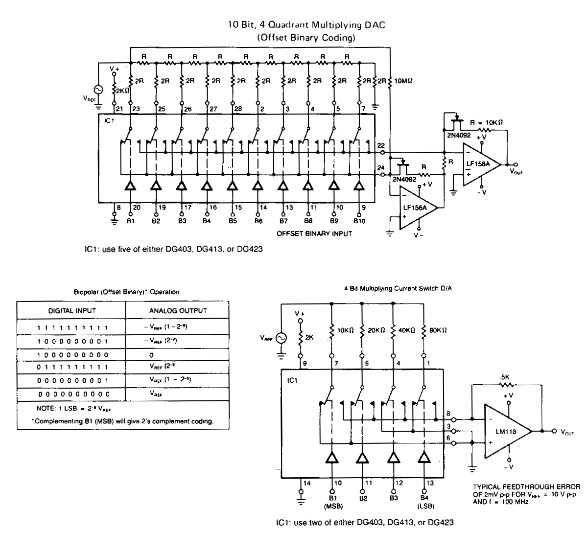
The following application circuits are designed to demonstrate several key concepts: A 2 kΩ resistor should be placed in series with the voltage source to limit supply current and mitigate negative ringing on the bit inputs. Temperature compensation for Rns(on)...
12-Bit dac with variable step size
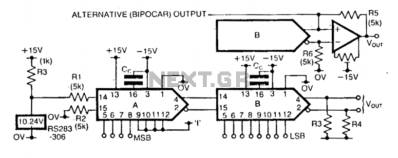
The step size of the converter is variable by selecting the high-order data bits. The first DAC, A, has a stable reference current supplied via a 10.24 V reference IC and resistor R1. Resistor R2 provides bias cancellation. Only the...