


Voltage-to-current converter
#voltage-to-current converter
#op-amp
#transistor
#Darlington pair
#current control
#negative current
#PNP
#circuit design
#high current
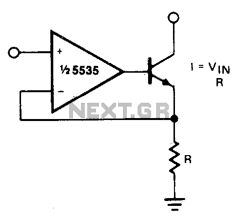
Description: The output current is Iqut = Vin/R. For negative currents, a PNP transistor can be utilized, and for improved accuracy, a Darlington pair may be substituted for the transistor. With careful design, this circuit can be employed to control currents of several amps. Additionally, unity gain compensation is essential.
The described circuit operates on the principle of current sensing and regulation, where the output current (Iqut) is determined by the input voltage (Vin) divided by a resistance (R). This configuration is typically used in applications requiring precise current control. The use of a PNP transistor allows for the management of negative currents, which is essential in certain circuit designs where the load may require reverse polarity operation.
In scenarios demanding higher current accuracy, substituting the standard PNP transistor with a Darlington pair is advisable. A Darlington pair consists of two bipolar junction transistors (BJTs) connected in such a way that the current amplified by the first transistor is fed into the second transistor, resulting in a significant increase in current gain. This configuration enhances the sensitivity and accuracy of the current sensing mechanism, making it suitable for applications where precision is paramount.
To ensure stability and prevent oscillations in the circuit, unity gain compensation is required. This involves adding a compensation capacitor in the feedback loop to maintain a stable gain across the operational range. The capacitor's value must be carefully calculated based on the circuit's frequency response and load conditions to achieve the desired performance without introducing phase shifts that could lead to instability.
Overall, with meticulous design considerations, this circuit can effectively manage high currents while maintaining accuracy and stability, making it a valuable component in various electronic applications such as power supplies, motor controllers, and current regulators.The current out is Iqut—Vin/R. For negative currents, a PNP can be used and, for better accuracy,-a Darlington pair can be substituted for the transistor. With careful design, this circuit can be used to control currents of many amps Unity gain compensation is necessary.
The described circuit operates on the principle of current sensing and regulation, where the output current (Iqut) is determined by the input voltage (Vin) divided by a resistance (R). This configuration is typically used in applications requiring precise current control. The use of a PNP transistor allows for the management of negative currents, which is essential in certain circuit designs where the load may require reverse polarity operation.
In scenarios demanding higher current accuracy, substituting the standard PNP transistor with a Darlington pair is advisable. A Darlington pair consists of two bipolar junction transistors (BJTs) connected in such a way that the current amplified by the first transistor is fed into the second transistor, resulting in a significant increase in current gain. This configuration enhances the sensitivity and accuracy of the current sensing mechanism, making it suitable for applications where precision is paramount.
To ensure stability and prevent oscillations in the circuit, unity gain compensation is required. This involves adding a compensation capacitor in the feedback loop to maintain a stable gain across the operational range. The capacitor's value must be carefully calculated based on the circuit's frequency response and load conditions to achieve the desired performance without introducing phase shifts that could lead to instability.
Overall, with meticulous design considerations, this circuit can effectively manage high currents while maintaining accuracy and stability, making it a valuable component in various electronic applications such as power supplies, motor controllers, and current regulators.The current out is Iqut—Vin/R. For negative currents, a PNP can be used and, for better accuracy,-a Darlington pair can be substituted for the transistor. With careful design, this circuit can be used to control currents of many amps Unity gain compensation is necessary.
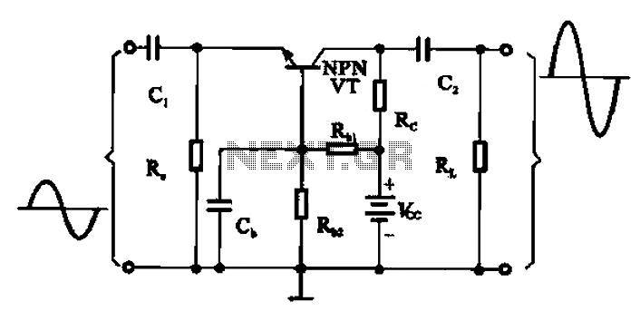
Common base transistor amplifier circuit of a unit
A common base transistor amplifier circuit is characterized by its basic structure, which includes key components such as a biasing resistor, capacitors for coupling, and an amplifying transistor. The circuit features four resistors that establish the quiescent point, with the...

Doppler Rdf
The power supply consists of a 7812 voltage regulator followed by an operational amplifier (op-amp) configured to output 6V, which serves as a midpoint supply voltage for the audio op-amp stages. A 12V regulator is deemed excessive for battery-powered applications....

Transistor Geiger Counter
One of the most unfortunate features of the typical portable Geiger counter is the short lifespan of the costly high-voltage batteries.
The limitation of high-voltage battery life in portable Geiger counters significantly affects their usability and operational efficiency. These devices are...
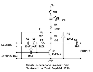
simple microphone preamplifier
The circuit is a simple one-transistor amplifier with an amplification factor of approximately 30-40 dB, which varies depending on the transistor, temperature, and voltage. The dynamic microphone input is a straightforward one-transistor amplifier circuit with no special features. LED D1...
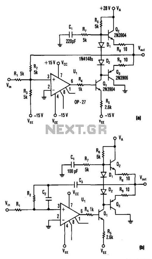
Compound Op Amp Vco Driver
This circuit produces a 5 to 25 V output to drive a voltage-controlled oscillator (VCO) from a standard ±15 V supply system. Resistor R7 and capacitor C1 provide frequency compensation. Transistors Q1 through Q3 form an inverting amplifier with a...
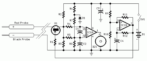
Quick On-Board Junction TesterCircuit
Acoustic check of transistor and diode junctions. Also suitable as a continuity tester. Short circuits or broken PCB tracks can be easily recognized.
The acoustic check of transistor and diode junctions is a method used to assess the functionality of these...
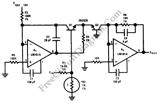
Anti-Log Converter
Anti-log or exponential generation involves rearranging logarithmic circuitry. The circuit diagram below illustrates the relevant circuitry.
Anti-logarithmic or exponential circuits are essential in various applications, particularly in signal processing and analog computing. These circuits typically utilize operational amplifiers (op-amps) configured in...
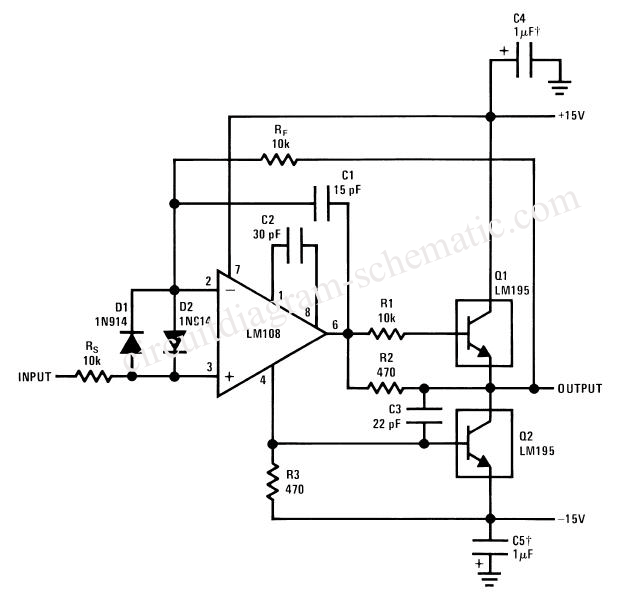
Amp Voltage Follower
A simple power operational amplifier circuit designed for operation up to 300 Hz. One variant of this circuit presents challenges in protecting the flow regulator due to its fixed nature, rendering standard protections ineffective. The circuit is intended to limit...
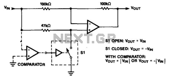
Programmable Inverter/Rectifier
The operational amplifier (op amp) can function as either an inverter or a buffer, depending on the polarity controlled by a switch. When configured as a buffer, the gain remains constant at 1. In contrast, when functioning as an inverter,...