


Voltage-to-current converters
#voltage-to-current
#converter
#operational amplifier
#transistor
#Darlington
#current control
#circuit design
#negative current
#accuracy
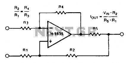
Description: A simple voltage-to-current converter is illustrated. The output current is given by 0t or Vjn/R. For negative currents, a PNP transistor can be employed, and for improved accuracy, a Darlington pair can replace the transistor. With meticulous design, this circuit can effectively control currents of several amps. Additionally, unity gain compensation is essential.
The voltage-to-current converter circuit operates by converting an input voltage signal into a proportional output current. The fundamental relationship governing the output current (I_out) is defined by the equation I_out = V_in / R, where V_in is the input voltage and R is the resistance connected in the feedback loop.
To achieve negative output currents, a PNP transistor can be utilized. This configuration allows for the inversion of the current flow, making it suitable for applications requiring negative current outputs. For applications demanding higher precision and improved linearity, substituting the single PNP transistor with a Darlington pair is advisable. The Darlington configuration consists of two transistors that provide a high current gain, thereby enhancing the performance of the converter.
The design of the circuit must consider factors such as power supply voltage, load characteristics, and thermal management to ensure reliable operation, especially when controlling currents in the range of several amps. Adequate heat sinking may be required to dissipate excess heat generated by the transistors under load conditions.
Unity gain compensation is a critical aspect of the circuit design, ensuring stability across a wide frequency range. This compensation technique involves adding a capacitor in the feedback loop, which helps to mitigate potential oscillations and ensures that the converter maintains a stable output under varying load conditions.
Overall, this voltage-to-current converter design offers versatility and precision for various applications, including signal conditioning, actuator control, and driving loads that require specific current levels.A simple voltage-to-current converter is shown in the figure. The current out is 0t or Vjn/R. For negative currents, a pnp can be used and, for better accuracy, a Darlington pah-can be substituted for the transistor. With careful design, this circuit can be used to control currents of many amps. Unity gain compensation is necessary.
The voltage-to-current converter circuit operates by converting an input voltage signal into a proportional output current. The fundamental relationship governing the output current (I_out) is defined by the equation I_out = V_in / R, where V_in is the input voltage and R is the resistance connected in the feedback loop.
To achieve negative output currents, a PNP transistor can be utilized. This configuration allows for the inversion of the current flow, making it suitable for applications requiring negative current outputs. For applications demanding higher precision and improved linearity, substituting the single PNP transistor with a Darlington pair is advisable. The Darlington configuration consists of two transistors that provide a high current gain, thereby enhancing the performance of the converter.
The design of the circuit must consider factors such as power supply voltage, load characteristics, and thermal management to ensure reliable operation, especially when controlling currents in the range of several amps. Adequate heat sinking may be required to dissipate excess heat generated by the transistors under load conditions.
Unity gain compensation is a critical aspect of the circuit design, ensuring stability across a wide frequency range. This compensation technique involves adding a capacitor in the feedback loop, which helps to mitigate potential oscillations and ensures that the converter maintains a stable output under varying load conditions.
Overall, this voltage-to-current converter design offers versatility and precision for various applications, including signal conditioning, actuator control, and driving loads that require specific current levels.A simple voltage-to-current converter is shown in the figure. The current out is 0t or Vjn/R. For negative currents, a pnp can be used and, for better accuracy, a Darlington pah-can be substituted for the transistor. With careful design, this circuit can be used to control currents of many amps. Unity gain compensation is necessary.
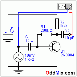
transistor amplifier self bias
The simplest way to bias a transistor amplifier is through a fixed-bias circuit. The supply voltage is connected to the base terminal of the transistor via the R1 current-limiting resistor. The bias resistor value is typically chosen based on the...
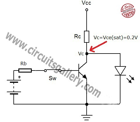
Transistor act as a switch
A transistor is a semiconductor device utilized for switching and amplifying weak signals. This article details the operation of a transistor and its function as a switch. Currently, transistors are integrated into most electronic equipment for switching applications, with digital...
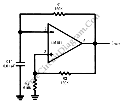
Operational Amplifier (Op-Amp) Oscillator
This is an operational amplifier (Op-Amp) oscillator circuit. This circuit has several advantages, including its ability to operate at low frequencies.
The operational amplifier oscillator circuit is designed to generate a periodic waveform output, typically a sine or square wave, using...
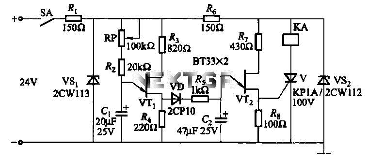
Three single junction transistor time relay circuits
This circuit consists of three single-junction transistor time relay circuits utilizing a pulse charging mechanism, allowing for extended delay times of up to several minutes. The first stage delay circuit incorporates unijunction transistors (VTi) and other components, where capacitor C1...
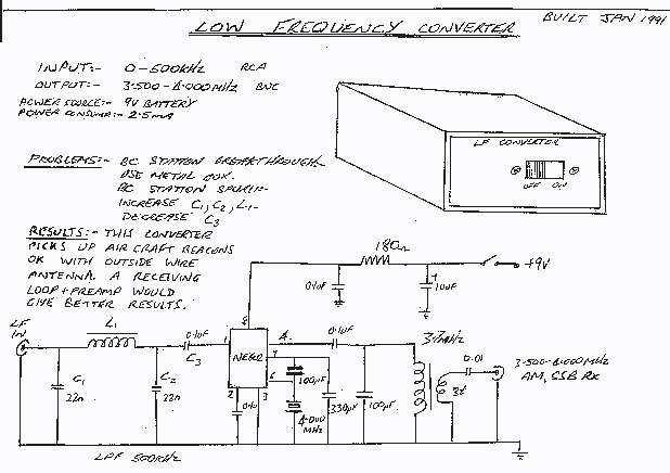
500kHz to 4 MHz Converter
This converter allows reception of signals below 500 kHz on a 3.5 to 4 MHz HF receiver. It should therefore be useful for those with receivers that do not receive the lower frequencies. Again the converter uses the popular NE602...
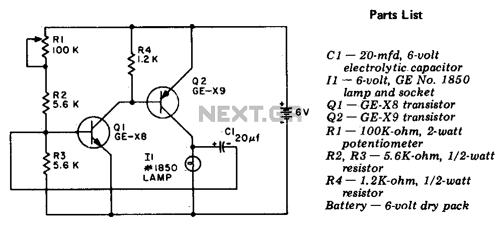
Flasher-light control
The circuit is a two-stage, direct-coupled transistor amplifier configured as a free-running multivibrator. Both the flash duration and flash interval can be adjusted by turning the potentiometer, R1.
The described circuit operates as a two-stage, direct-coupled transistor amplifier, functioning as a...
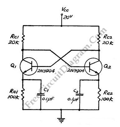
Direct Coupled Discrete Astable Multivibrator circuit
This flip-flop circuit functions as a free-running astable multivibrator, where the bases and collectors of both emitter-biased transistors are directly coupled. The switching action is facilitated by a capacitor in each emitter circuit, resulting in the generation of triangle waves...
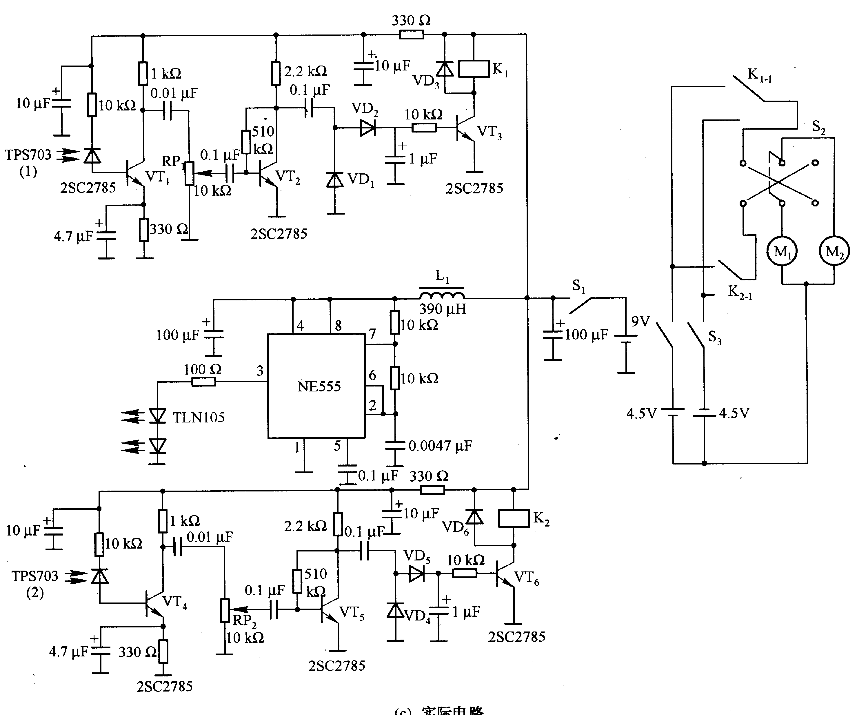
Robot control circuit composed of transistor and NE555
Figure 2-33 (a) illustrates the schematic diagram of a robot approaching an object. When no objects are detected in front of the robot, it moves forward in a straight line. If an object is detected on the left or right...
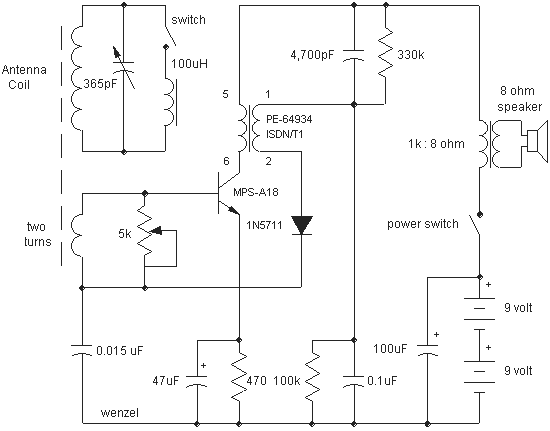
Simple Transistor Reflex Receivers
This reflex radio project was inspired by Robert Bazian's design. His reflex radio is the "darndest" thing I have seen and his spectacular results inspired me to come up with my own version! These designs are similar to two-transistor circuits...