


Voltage to Current Convertor using LM723 Project PCB
#LM723
#voltage to current converter
#process control
#current loop
#signal conversion
#opamp
#industrial control
#analog circuit
#three wire
#control system
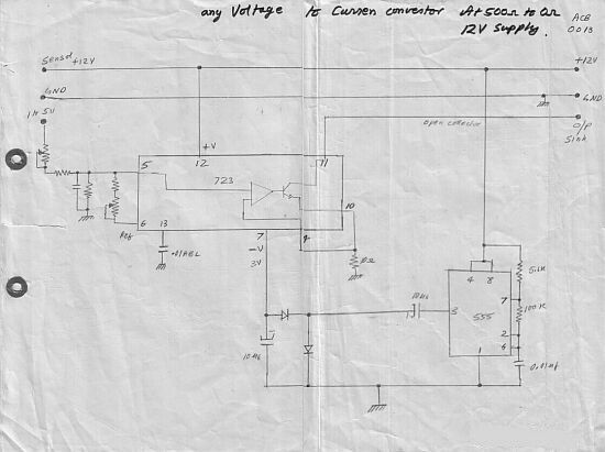
Description: This circuit converts a voltage control output from a process controller into a current control signal, which is necessary when an AC drive or valve requires a current control signal. It operates as a three-wire voltage-to-current loop converter. A 1-5 V DC signal is attenuated and fed to pin 5 of the LM723 op-amp section, which aims to maintain the same voltage at pin 10. This configuration produces an open collector constant current sink that is proportional to the 1-5 V input. By adjusting the attenuator, the 1-5 V input can be calibrated to provide a 4-20 mA output, allowing multiple instruments to be connected in series, such as a controller, recorder, or PLC. With a supply voltage of up to 24 V, three instruments can be connected in this manner. Additionally, a connection to pin 6 is necessary to convert a 0-1 V input into a 4-20 mA output.
The circuit effectively utilizes the LM723 voltage regulator, which is configured as an operational amplifier in this application. The input voltage range of 1-5 V DC is crucial for the operation, as it is the control signal that dictates the output current. The attenuation process is essential for ensuring that the input voltage is scaled appropriately to match the desired output current range of 4-20 mA, which is a standard for many industrial control systems.
The open collector configuration of the output allows for flexibility in connecting multiple devices in series without the risk of affecting the operation of each device. The current sink design ensures that the output current remains constant, regardless of variations in load, as long as the input voltage remains within the specified range.
The operation of the LM723 as an op-amp involves feedback mechanisms that maintain the desired output. The calibration process through the attenuator enables precise adjustments to be made, ensuring that the output is accurately reflective of the input voltage. This is particularly important in applications where accurate control signals are necessary for the operation of devices such as valves or AC drives.
Furthermore, the ability to connect up to three instruments with a supply voltage of 24 V enhances the versatility of the circuit, making it suitable for various applications in industrial settings. The inclusion of a connection to pin 6 for converting a 0-1 V input to a 4-20 mA output adds another layer of functionality, allowing the circuit to accommodate different input signal types.
In summary, this voltage-to-current loop converter circuit is a robust solution for converting control signals in various industrial applications, providing reliable and accurate current outputs for effective control of AC drives, valves, and other instrumentation.Circuit This Circuit converts a voltage control output from a Process Controller to be converted into a Current Control if the AC-Drive or Valve needs a Current Control Signal. This is a three wire voltage to current loop converter. The 1-5 V DC is attenuated and fed to pin 5 LM723 opamp section which tries to maintain the same voltage at pin 10 a
cross the 10 E, thereby producing a open collector constant current sink proportional to the 1-5V input. By trimming the attenuator you can scale- calibrate 1-5V input to 4-20mA output for looping many instruments in series, like a controller, recorder or PLC.
With a supply voltage upto 24V, three instruments can be looped. The connection to pin 6 is required to convert 0-1 input to 4-20mA.
The circuit effectively utilizes the LM723 voltage regulator, which is configured as an operational amplifier in this application. The input voltage range of 1-5 V DC is crucial for the operation, as it is the control signal that dictates the output current. The attenuation process is essential for ensuring that the input voltage is scaled appropriately to match the desired output current range of 4-20 mA, which is a standard for many industrial control systems.
The open collector configuration of the output allows for flexibility in connecting multiple devices in series without the risk of affecting the operation of each device. The current sink design ensures that the output current remains constant, regardless of variations in load, as long as the input voltage remains within the specified range.
The operation of the LM723 as an op-amp involves feedback mechanisms that maintain the desired output. The calibration process through the attenuator enables precise adjustments to be made, ensuring that the output is accurately reflective of the input voltage. This is particularly important in applications where accurate control signals are necessary for the operation of devices such as valves or AC drives.
Furthermore, the ability to connect up to three instruments with a supply voltage of 24 V enhances the versatility of the circuit, making it suitable for various applications in industrial settings. The inclusion of a connection to pin 6 for converting a 0-1 V input to a 4-20 mA output adds another layer of functionality, allowing the circuit to accommodate different input signal types.
In summary, this voltage-to-current loop converter circuit is a robust solution for converting control signals in various industrial applications, providing reliable and accurate current outputs for effective control of AC drives, valves, and other instrumentation.Circuit This Circuit converts a voltage control output from a Process Controller to be converted into a Current Control if the AC-Drive or Valve needs a Current Control Signal. This is a three wire voltage to current loop converter. The 1-5 V DC is attenuated and fed to pin 5 LM723 opamp section which tries to maintain the same voltage at pin 10 a
cross the 10 E, thereby producing a open collector constant current sink proportional to the 1-5V input. By trimming the attenuator you can scale- calibrate 1-5V input to 4-20mA output for looping many instruments in series, like a controller, recorder or PLC.
With a supply voltage upto 24V, three instruments can be looped. The connection to pin 6 is required to convert 0-1 input to 4-20mA.
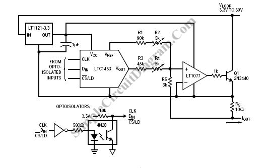
Computer-Controlled 4-20mA Current Loop
In certain industries, a computer-controlled 4-20 mA current loop is utilized to manage various equipment. This current loop is employed to transmit a signal over a distance.
The 4-20 mA current loop is a standard method for transmitting analog signals in...
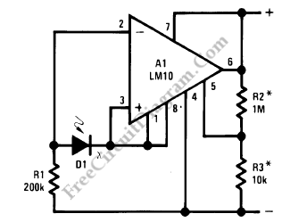
Current Loop Light Level Detector
This circuit is a two-wire light level detector. The power supply and output signal are delivered through the same wires, utilizing a current loop.
This two-wire light level detector circuit operates by using a single pair of wires for both power...
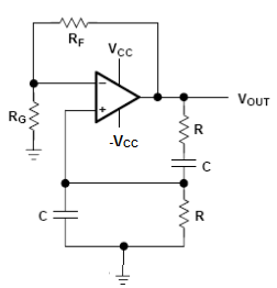
What is the name of this OpAmp Circuit
I have been researching a "mystery circuit" and I cannot determine its name. Assistance is requested.
The inquiry pertains to an unidentified electronic circuit, often referred to as a "mystery circuit." Such circuits can encompass a wide range of configurations and...
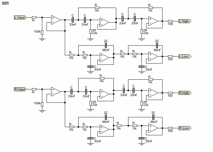
Loudness control
An operational amplifier such as the NE5532 should be used. The desired frequency must be calculated for each block: one for flat, one for bass, and one for high frequencies. It is important to include a buffer at the first...
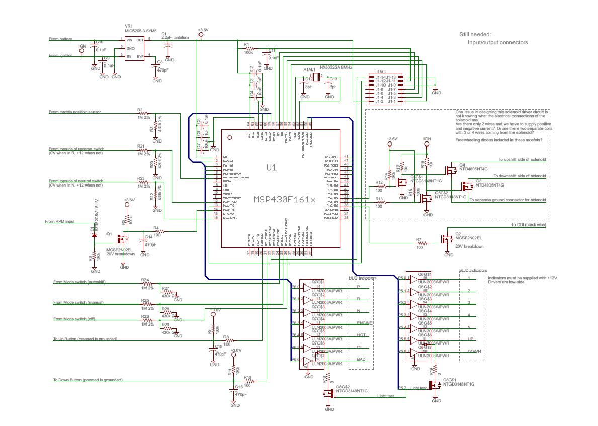
Electrical_Subsystem
The following data and mapping pertain to the 2-D shift mapping algorithm that the controller will utilize to determine when and if a shift should occur. The solid lines on the graph indicate up-shift boundaries, while the dashed lines represent...
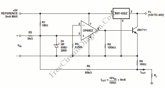
OP90 4 mA to 20 mA Current Loop Transmitter
An output of 4 mA to 20 mA that is linearly proportional to the input voltage is provided by the current transmitter. Line rejection is included.
The current transmitter operates within a specified range, providing an output current that is directly...
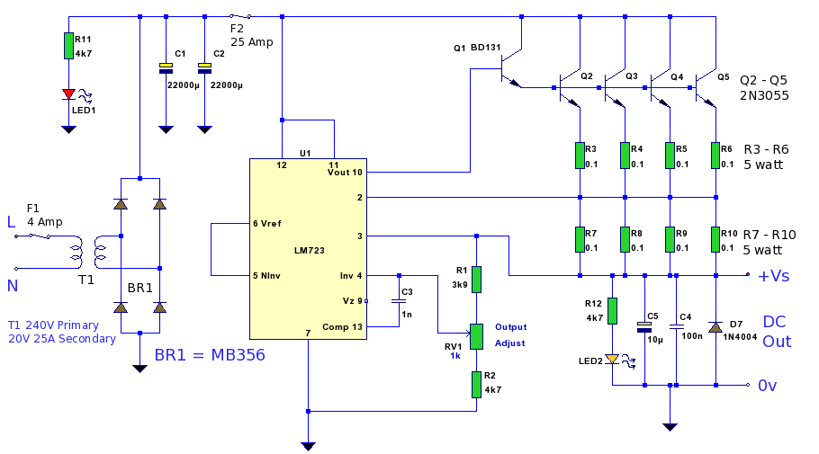
12 Volt 20 Amp Power Supply
A 12 Volt high current 20 Amp power supply. The output voltage is variable from 12.2 Volt to 14.4V, allowing it to be set for any device requiring voltage and current in that range. This power supply unit (PSU) utilizes...
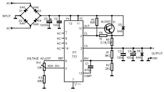
lm723 variable power supply circuit design
This LM723 variable power supply circuit design is a straightforward variable power supply capable of delivering an output voltage ranging from 8 to 30 volts, with a maximum output current of 3 amperes. The circuit features a low output ripple...
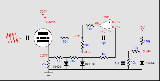
Broskie auto-bias circuit
It is embarrassing to acknowledge that the blog post from April 29 contained several schematic errors of my own making, particularly in the variation of Morgan Jones's circuit. One of the resistor values was incorrect by a factor of ten,...