


wide range current pumps for precision
#current pump
#precision
#phase locked loop
#op-amp
#wide range
#resistors
#voltage
#semiprecision
#output current
#circuit design
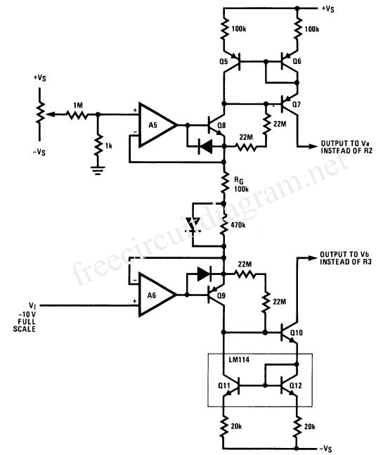
Description: The wide-range current pump for the precision phase-locked loop (PLL) circuit is a semi-precision circuit that provides an output current proportional to -V1, with a variation of approximately 10 to 15%, across a three-decade range. The 22 MΩ resistors are included to prevent the current from shutting off in the event that -V becomes positive, although this may be unnecessary if amplifier A4 is utilized. For optimal performance across the entire three-decade range (from 11 kHz to 9 Hz), it is recommended to use amplifier A4, remove the four 22 MΩ resistors, and connect a diode in parallel with the 470 kΩ resistor in series with RG as illustrated. This configuration ensures stability at all frequencies, although achieving stability below 1/1500 of full scale requires additional measures. The PLL is commonly employed in the testing of voltage-to-frequency converters (VFCs), as it enables the LM331 to operate at a crystal-controlled frequency (designated as the F input). The output voltage at VOUT can be quickly measured using a 6-digit digital voltmeter with a maximum nonlinearity of 1 ppm, offering significantly faster and more precise measurements than those obtained by forcing a voltage and attempting to read a frequency. The advantages of this method are particularly evident at 10 kHz, but even more pronounced at 50 Hz. Measuring a 50 Hz signal with a resolution of ±0.01 Hz cannot be achieved as accurately, quickly, or conveniently as the PLL's voltage output settles.
The wide-range current pump integrated into the precision phase-locked loop (PLL) circuit serves as a critical component in high-accuracy measurement systems. This semi-precision circuit is designed to produce an output current that is inversely proportional to a negative voltage input (-V1), exhibiting a tolerance of 10 to 15%. The design includes 22 MΩ resistors, which serve to maintain current flow in scenarios where the negative voltage may inadvertently become positive, although their necessity is conditional based on the configuration of the operational amplifier A4.
For optimal performance across the specified frequency range of 11 kHz to 9 Hz, the circuit should be modified by removing the 22 MΩ resistors and incorporating a diode in parallel with a 470 kΩ resistor in series with RG. This modification is crucial for enhancing stability across the frequency spectrum, although it is noted that achieving stability at frequencies below 1/1500 of full scale will require additional design considerations.
The PLL circuit is particularly advantageous in the context of testing voltage-to-frequency converters (VFCs). By allowing the LM331 to operate at a frequency determined by a crystal oscillator (denoted as the F input), the circuit facilitates rapid and precise voltage measurements at the output terminal VOUT. The use of a high-resolution 6-digit digital voltmeter with a maximum nonlinearity of 1 ppm greatly enhances measurement accuracy, enabling faster data acquisition compared to traditional methods that involve forcing a voltage and measuring the resultant frequency.
The benefits of employing this PLL configuration are especially notable at higher frequencies, such as 10 kHz, where the system's response is both rapid and reliable. The advantages become even more pronounced at lower frequencies, such as 50 Hz, where achieving a resolution of ±0.01 Hz poses significant challenges using conventional measurement techniques. The PLL's ability to provide a stable voltage output simplifies the measurement process, making it an invaluable tool in precision electronic applications.The wide-range current pump for the precision phase locked loop circuit is a semiprecision circuit, and provides an output current proportional to -V1, give or take 10 or 15%, over a 3-decade range. The 22 MW resistors prevent the current from shutting off in case -V becomes positive (probably unnecessary if A4 is used).
For best results over a full 3-decade range (11 kHz to 9 Hz), do use A4, delete the four 22 MW resistors, and insert the (diode parallel to the 470 kW) in series with the RG as shown. This will give good stability at all frequencies (although stability cannot be extended below 1/1500 of full scale without extra efforts).
This is a picture schematic: This PLL has been widely used in testing of VFCs, as it can force the LM331 to run at a crystal-controlled frequency (established as the F input), and the output voltage at VOUT is promptly measured by a 6-digit (1 ppm nonlinearity, max) digital voltmeter, with much greater speed and precision than can be obtained by forcing a voltage and trying to read a frequency. While at 10 kHz, the advantages are clearcut; at 50 Hz it is even more obvious. Measuring a 50 Hz signal with ±0. 01 Hz resolution cannot be done (even with the most powerful computing counter-timer) as accurately, quickly, and conveniently as the PLL`s voltage output settles.
The wide-range current pump integrated into the precision phase-locked loop (PLL) circuit serves as a critical component in high-accuracy measurement systems. This semi-precision circuit is designed to produce an output current that is inversely proportional to a negative voltage input (-V1), exhibiting a tolerance of 10 to 15%. The design includes 22 MΩ resistors, which serve to maintain current flow in scenarios where the negative voltage may inadvertently become positive, although their necessity is conditional based on the configuration of the operational amplifier A4.
For optimal performance across the specified frequency range of 11 kHz to 9 Hz, the circuit should be modified by removing the 22 MΩ resistors and incorporating a diode in parallel with a 470 kΩ resistor in series with RG. This modification is crucial for enhancing stability across the frequency spectrum, although it is noted that achieving stability at frequencies below 1/1500 of full scale will require additional design considerations.
The PLL circuit is particularly advantageous in the context of testing voltage-to-frequency converters (VFCs). By allowing the LM331 to operate at a frequency determined by a crystal oscillator (denoted as the F input), the circuit facilitates rapid and precise voltage measurements at the output terminal VOUT. The use of a high-resolution 6-digit digital voltmeter with a maximum nonlinearity of 1 ppm greatly enhances measurement accuracy, enabling faster data acquisition compared to traditional methods that involve forcing a voltage and measuring the resultant frequency.
The benefits of employing this PLL configuration are especially notable at higher frequencies, such as 10 kHz, where the system's response is both rapid and reliable. The advantages become even more pronounced at lower frequencies, such as 50 Hz, where achieving a resolution of ±0.01 Hz poses significant challenges using conventional measurement techniques. The PLL's ability to provide a stable voltage output simplifies the measurement process, making it an invaluable tool in precision electronic applications.The wide-range current pump for the precision phase locked loop circuit is a semiprecision circuit, and provides an output current proportional to -V1, give or take 10 or 15%, over a 3-decade range. The 22 MW resistors prevent the current from shutting off in case -V becomes positive (probably unnecessary if A4 is used).
For best results over a full 3-decade range (11 kHz to 9 Hz), do use A4, delete the four 22 MW resistors, and insert the (diode parallel to the 470 kW) in series with the RG as shown. This will give good stability at all frequencies (although stability cannot be extended below 1/1500 of full scale without extra efforts).
This is a picture schematic: This PLL has been widely used in testing of VFCs, as it can force the LM331 to run at a crystal-controlled frequency (established as the F input), and the output voltage at VOUT is promptly measured by a 6-digit (1 ppm nonlinearity, max) digital voltmeter, with much greater speed and precision than can be obtained by forcing a voltage and trying to read a frequency. While at 10 kHz, the advantages are clearcut; at 50 Hz it is even more obvious. Measuring a 50 Hz signal with ±0. 01 Hz resolution cannot be done (even with the most powerful computing counter-timer) as accurately, quickly, and conveniently as the PLL`s voltage output settles.
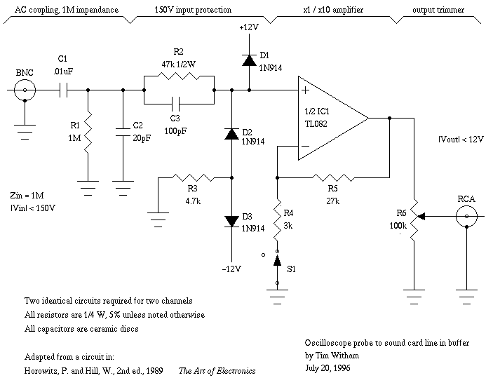
Capacitor in parallel with resistor on xoscope amplifier schematic
For capacitor C3, a 100pF capacitor is placed across resistor R2. The circuit functions similarly to previous configurations, although no explanation is provided. The purpose of this component may be self-evident to experienced users, but it may not be clear...
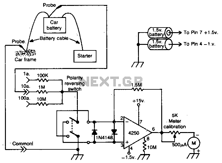
Auto battery current analyzer
This operational amplifier (op-amp) analyzer is designed to measure the current drawn by any device in a vehicle. It operates by detecting the minute voltage that develops across the battery cables when current flows.
To calibrate the unit, the current flow...
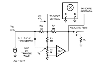
Op Amp Classic Gain and Linearity Testing
The diagram below illustrates a classic test fixture that has been utilized for an extended period to assist individuals in addressing non-linearity errors.
The classic test fixture depicted in the diagram serves as a fundamental tool in electronics testing and calibration....
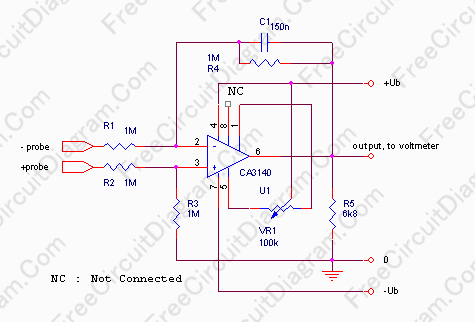
Single Input to Differential Input Adapter for Digital Voltmeter
In some cases, a differential input is needed for voltage measurement. By using a single operational amplifier, it is possible to construct an adapter that provides a floating voltage reference.
To achieve a differential input for voltage measurement using an operational...
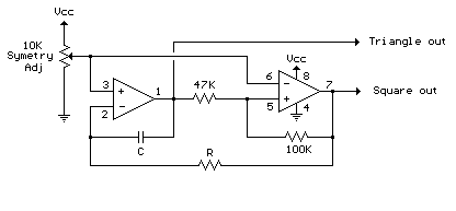
Audio Triangle Square Wave Generator Using Op-Amp
The circuit illustrates a straightforward triangle and square wave generator utilizing a common dual operational amplifier, the LM1558, capable of producing very low frequencies around 10 kHz. The time interval for one half-cycle is approximately determined by the product of...
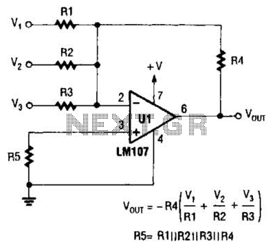
Inverting Summing Amplifier Circuit
The output of Ul is the sum of Vv, multiplied by the ratio of Rx to Rv, RJRV, and respectively. Resistors R1, R2, and R3 are selected as required for individual gains. Additionally, R4 influences the gain of all these...
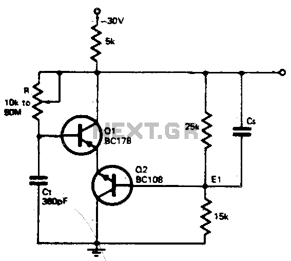
Wide range oscillator
The timing resistor R can be adjusted to any value between 10 kΩ and 50 MΩ to achieve a frequency range from 400 kHz to 100 Hz. Connecting the timing resistor to the collector of Q1 ensures that Q1 receives...
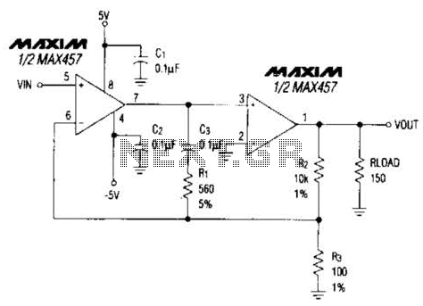
High Gbw Op-Amp Circuit
A composite amplifier can be constructed that offers high gain, wide bandwidth, and good DC accuracy by cascading the sections of a dual video amplifier and incorporating two suitable phase compensation components. The operational amplifier drives a 150-ohm load and...
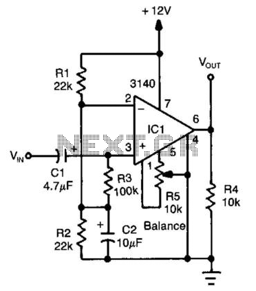
Sine-Wave/Square-Wave Converter
An operational amplifier (op amp) configured as a comparator generates a 10-V peak-to-peak square wave output with a 100-mV input signal, operating up to 15 kHz. Adjust resistor R5 to achieve symmetry in the square wave at low input levels.
The...