


XTR110 circuit diagram using an external PNP transistor
#XTR110
#PNP transistor
#Darlington pair
#current expansion
#output current
#discrete transistors
#circuit diagram
#signal conditioning
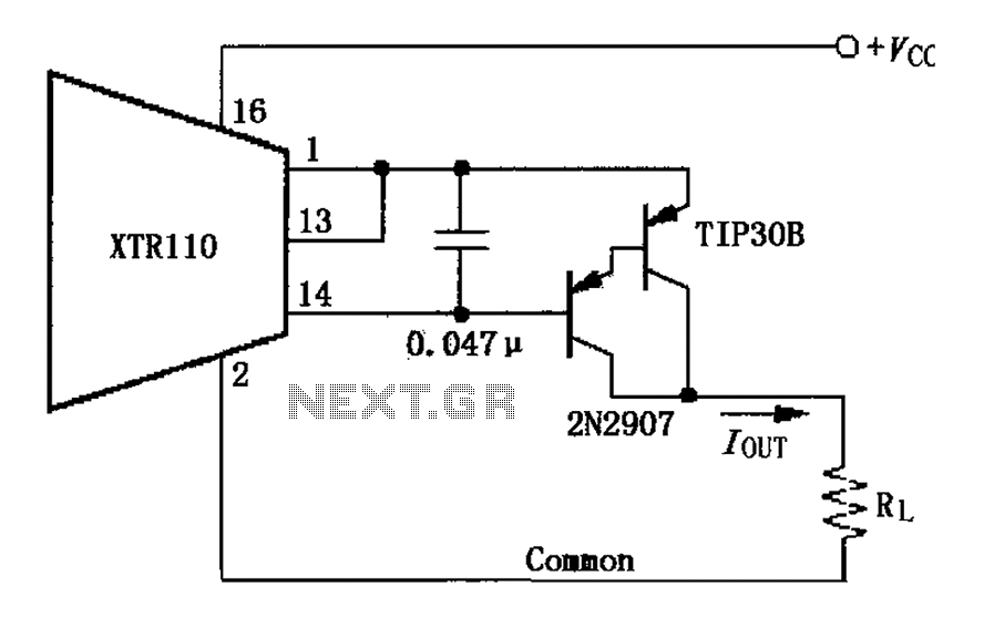
Description: The circuit consists of two discrete PNP Darlington transistors that form the external PNP transistor QEXT circuit to enhance output current. The use of integrated Darlington transistors is not recommended, as the internal base-emitter resistor can introduce additional errors. The power of the triode is dependent on the supply voltage and the full-scale output current, PMAX VCCIOUT.
The described circuit employs two discrete PNP Darlington transistors to create a robust output stage capable of delivering high current levels. The configuration of the transistors as a Darlington pair allows for a significant increase in current gain, making it suitable for applications requiring substantial output current without compromising signal integrity.
In this arrangement, the first transistor serves to amplify the input signal, while the second transistor further amplifies the current, resulting in a high output current capability. The choice of discrete transistors over integrated solutions is critical; integrated Darlington transistors often have internal base-emitter resistors that can lead to inaccuracies in the output due to variations in thermal characteristics and manufacturing tolerances. By using discrete components, the designer can better control these parameters, ensuring more reliable performance.
The circuit's power handling capability is influenced by the supply voltage (VCC) and the maximum output current (IOUT) specified for the application. The maximum power dissipation (PMAX) of the transistors must be carefully calculated to prevent thermal overload, and appropriate heat sinking may be required to maintain operational stability. The overall design must also consider the input and output impedance, ensuring compatibility with the preceding and following stages in the circuit.
In summary, the outlined circuit leverages the advantages of discrete PNP Darlington transistors to achieve high output current while mitigating the drawbacks associated with integrated solutions. Proper attention to component selection and thermal management is essential for optimal performance in demanding electronic applications. As shown, the circuit consisting of two discrete PNP Darlington transistors constituting the external PNP transistor QEXT circuit to expand output current. Here we do not advoc ate the use of integrated Darlington, Darlington because integrated inside the base - emitter resistor will cause additional errors. Triode power depends on the supply voltage and the full-scale output current, PMAX VCCIOUT
The described circuit employs two discrete PNP Darlington transistors to create a robust output stage capable of delivering high current levels. The configuration of the transistors as a Darlington pair allows for a significant increase in current gain, making it suitable for applications requiring substantial output current without compromising signal integrity.
In this arrangement, the first transistor serves to amplify the input signal, while the second transistor further amplifies the current, resulting in a high output current capability. The choice of discrete transistors over integrated solutions is critical; integrated Darlington transistors often have internal base-emitter resistors that can lead to inaccuracies in the output due to variations in thermal characteristics and manufacturing tolerances. By using discrete components, the designer can better control these parameters, ensuring more reliable performance.
The circuit's power handling capability is influenced by the supply voltage (VCC) and the maximum output current (IOUT) specified for the application. The maximum power dissipation (PMAX) of the transistors must be carefully calculated to prevent thermal overload, and appropriate heat sinking may be required to maintain operational stability. The overall design must also consider the input and output impedance, ensuring compatibility with the preceding and following stages in the circuit.
In summary, the outlined circuit leverages the advantages of discrete PNP Darlington transistors to achieve high output current while mitigating the drawbacks associated with integrated solutions. Proper attention to component selection and thermal management is essential for optimal performance in demanding electronic applications. As shown, the circuit consisting of two discrete PNP Darlington transistors constituting the external PNP transistor QEXT circuit to expand output current. Here we do not advoc ate the use of integrated Darlington, Darlington because integrated inside the base - emitter resistor will cause additional errors. Triode power depends on the supply voltage and the full-scale output current, PMAX VCCIOUT
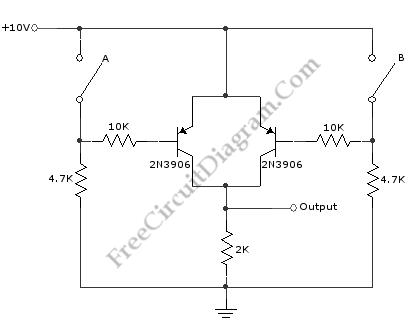
Basic Logic Gate with PNP Transistor
This schematic diagram illustrates a basic logic gate circuit. This PNP transistor circuit can function as either an OR gate or an AND gate, depending on the input states.
The described circuit employs PNP transistors to create a versatile logic gate...
Signal Conditioners Information
Signal conditioning involves a series of operations applied to a signal to make it compatible for interfacing with other devices or systems. Signal conditioners are the devices that execute this operation, featuring both an input and an output. Typically, the...
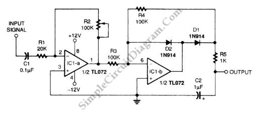
Averager and Peak Hold/Extender Signal Conditioner
A signal averager circuit can be formed by an amplifier and active signal rectifier, which is implemented using two operational amplifiers in this circuit.
The signal averager circuit utilizes two operational amplifiers (op-amps) to achieve signal averaging through amplification and rectification....
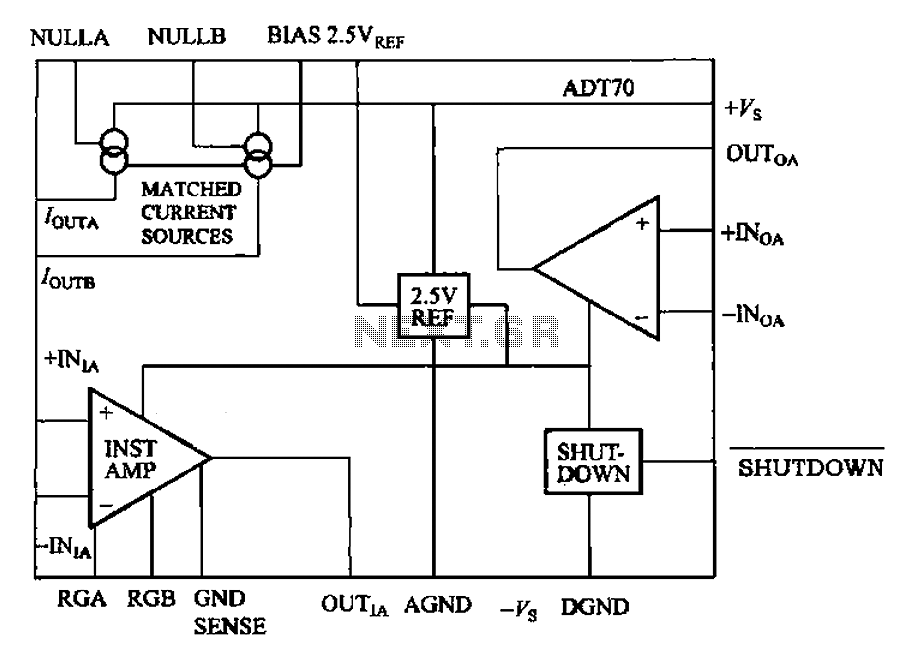
ADT70 internal functional block diagram
The ADI I70 is a signal conditioning integrated circuit designed for RTD/PRTD applications, particularly suitable for 1K and 100Ω platinum RTDs (PRTDs). The ADT70 features an integrated instrumentation amplifier, an operational amplifier, a 2.5V reference power supply, and a matching...
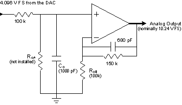
Signal Conditioning Analog Front-end for Microcontrollers
The I/O board incorporates 16-bit resolution voltage analog inputs and outputs, along with a 4-20mA current loop transmitter and receiver for microcontroller applications. The document discusses amplifier circuits and schematics, including a signal conditioning variable gain amplifier, analog filter, and...
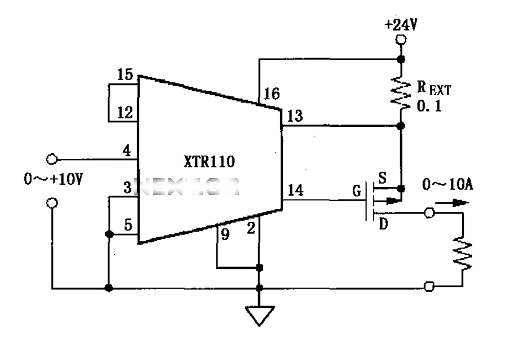
XTR110 voltage - current converter circuit diagram
When the output current exceeds 40mA, the XTR110 requires the use of an external resistor (REXT) instead of the internal 50-ohm resistor (R9). REXT should be connected between pin 13 and pin 1. The value of REXT is determined based...
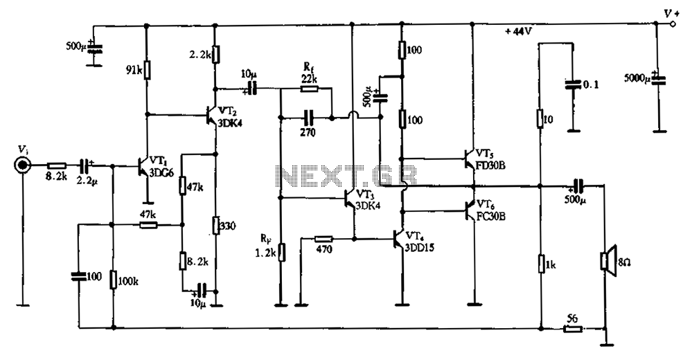
Darlington amplifier
The circuit schematic depicted in Figure 2-3 illustrates a twin direct-coupled input amplifier stage composed of components OV, RLR, and VT2. The emitter of VT2 is connected to the base of VT3, utilizing local feedback to stabilize its DC operating...
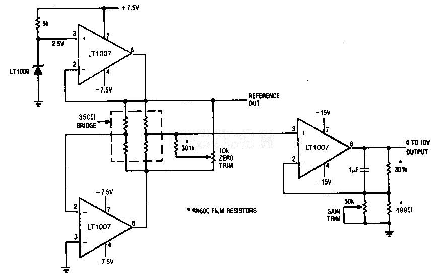
Signal-conditioner-with-bridge
The LT1007 is capable of providing excitation current directly to bias the 350-0 bridge at 5 V. With only 5 V across the bridge, as opposed to the usual 10 V, total power dissipation and bridge warm-up drift is reduced....
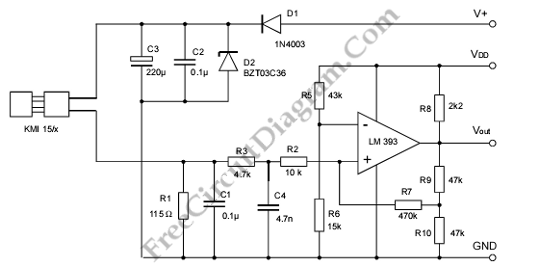
Signal Conditioning Circuit for KMI 15/x Rotation Speed Sensor
A modulated current is supplied by the integrated rotational speed sensor KMI 15/x. This current signal needs to be converted into a ground-referenced voltage signal.
The KMI 15/x sensor operates by generating a modulated current proportional to the rotational speed of...