


1 Hz Generator and 2 Hertz Oscillator Circuit
#4060
#4013
#frequency generator
#rectangular wave
#counter
#signal generator
#low frequency
#CMOS
#digital oscillator
#timing circuit
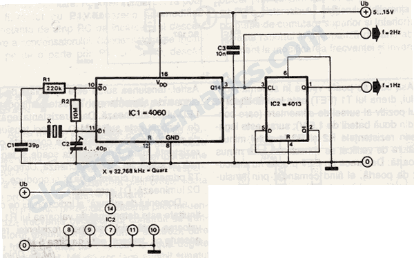
Description: This 1 Hz and 2 Hz generator or oscillator is constructed using a 4060 IC as the oscillator and a 14-bit counter. To achieve a 1 Hz signal from the 4060, a 1/2 4013 flip-flop is utilized. This circuit generates a rectangular voltage waveform with an amplitude ranging from 0V to the power supply voltage.
The circuit operates by leveraging the 4060 integrated circuit, which combines an oscillator and a binary counter. The oscillator portion of the 4060 is typically configured to produce a square wave output that can be divided down to lower frequencies. In this design, the output frequency is set to 2 Hz, which is subsequently divided by two using the 1/2 4013 flip-flop to yield a stable 1 Hz output signal.
The 4060 IC operates based on an external resistor-capacitor (RC) network that determines the oscillation frequency. The frequency can be calculated using the formula:
\[ f = \frac{1}{2 \cdot R \cdot C \cdot (N + 1)} \]
where \( R \) is the resistance in ohms, \( C \) is the capacitance in farads, and \( N \) is the division factor set by the counter. The resulting square wave output from the 4060 can be fed into the 4013 flip-flop, which is configured in toggle mode. This configuration divides the frequency by two, allowing for the generation of a precise 1 Hz signal.
The output of the circuit is a rectangular waveform that oscillates between 0V and the supply voltage, making it suitable for various applications, including clock generation for digital circuits, timing applications, and frequency modulation. Proper decoupling capacitors should be placed near the power supply pins of the ICs to ensure stable operation and minimize noise. Additionally, the circuit should be designed with appropriate power ratings and tolerances to ensure reliability during operation.This 1 Hz and 2Hz generator or oscillator is built with 4060 as an oscillator and a 14 bits counter. To obtain a 1Hz signal after 4060 we use 1/2 4013. This circuit provides a rectangular voltage with a amplitude between 0V and the power supply voltage.
The circuit operates by leveraging the 4060 integrated circuit, which combines an oscillator and a binary counter. The oscillator portion of the 4060 is typically configured to produce a square wave output that can be divided down to lower frequencies. In this design, the output frequency is set to 2 Hz, which is subsequently divided by two using the 1/2 4013 flip-flop to yield a stable 1 Hz output signal.
The 4060 IC operates based on an external resistor-capacitor (RC) network that determines the oscillation frequency. The frequency can be calculated using the formula:
\[ f = \frac{1}{2 \cdot R \cdot C \cdot (N + 1)} \]
where \( R \) is the resistance in ohms, \( C \) is the capacitance in farads, and \( N \) is the division factor set by the counter. The resulting square wave output from the 4060 can be fed into the 4013 flip-flop, which is configured in toggle mode. This configuration divides the frequency by two, allowing for the generation of a precise 1 Hz signal.
The output of the circuit is a rectangular waveform that oscillates between 0V and the supply voltage, making it suitable for various applications, including clock generation for digital circuits, timing applications, and frequency modulation. Proper decoupling capacitors should be placed near the power supply pins of the ICs to ensure stable operation and minimize noise. Additionally, the circuit should be designed with appropriate power ratings and tolerances to ensure reliability during operation.This 1 Hz and 2Hz generator or oscillator is built with 4060 as an oscillator and a 14 bits counter. To obtain a 1Hz signal after 4060 we use 1/2 4013. This circuit provides a rectangular voltage with a amplitude between 0V and the power supply voltage.
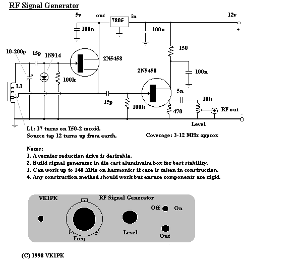
Signal Generators Circuits
Converting periodic waveforms to square waves is essential for extracting clock signals from data, creating waveform generators, and developing timing-pulse generators. A square-wave conversion circuit is more advantageous when the duty cycle of the square wave is variable and controllable....
Constitute a CMOS circuit time adjustment of a spot welder
This document outlines a CMOS circuit designed for time adjustment in a spot welder. The circuit allows for the selection of a number of cycles, ranging from 1 to 99, with practical applications typically using around 10 cycles. The schematic...
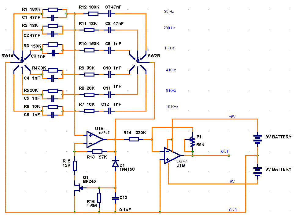
Oscillator circuit
This circuit is a low-frequency Wien bridge sinusoidal oscillator designed for the audio range, characterized by very low distortion, making it suitable for testing various audio equipment. The circuit has undergone thorough testing, and a printed circuit board (PCB) is...
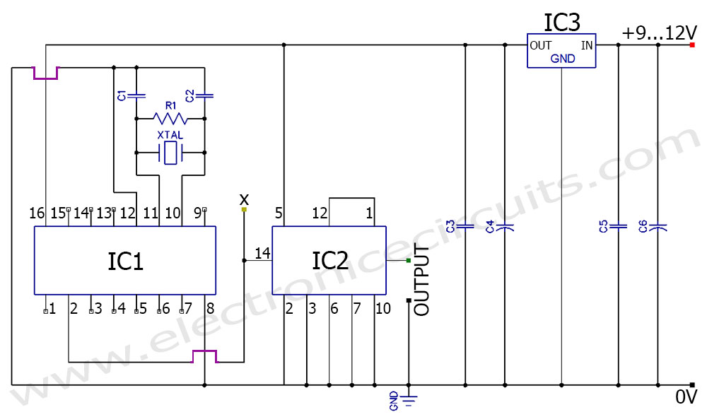
50Hz 60Hz Frequency Generator Circuit Using Crystal Oscillator
A frequency generator circuit capable of producing 50 Hz and 60 Hz outputs using a crystal oscillator. This oscillator can be utilized to generate precise frequency signals.
This frequency generator circuit employs a crystal oscillator as its core component, which ensures...
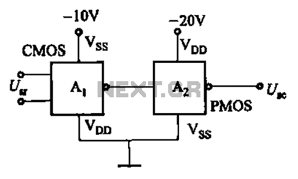
CMOS and PMOS cross interface circuit b
CMOS and PMOS cross interface circuit with PMOS integrated circuit providing high input impedance, allowing the input current to be negligible. The CMOS and PMOS interface circuit is illustrated in the accompanying figure.
The CMOS and PMOS cross interface circuit is...
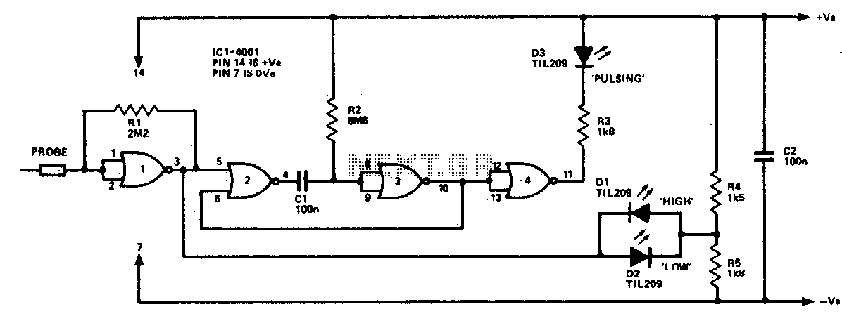
Cmos logic probe
The logic probe can indicate four input states, as follows: floating input - all LEDs off; logic 0 input - D2 switched on (D3 will briefly flash on); logic 1 input - D1 switched on; pulsing input - D3 switched...
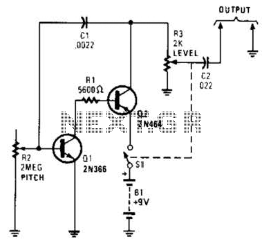
Signal Generator Circuit
Useful for troubleshooting audio, video, and lower frequency RF amplifiers. This circuit generates a signal that is rich in harmonics.
The circuit designed for troubleshooting audio, video, and lower frequency RF amplifiers is crucial for diagnosing issues in these systems. It...
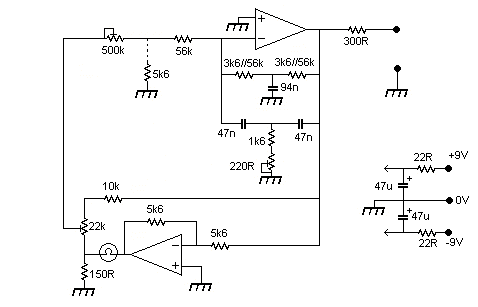
Signal Generator circuit
The output level was set to 3.8V peak to peak. The initial objective was to compare several different operational amplifiers (op-amps) before further optimizing the circuit. The op-amps evaluated were the TL072, LM4562, and OPA2134. The distortion spectra are presented...
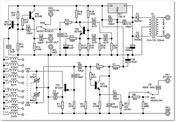
RF Signal Generator circuit
This signal generator is designed for the realignment of radio receivers. The unit is inexpensive and relatively simple but adequately serves its intended purpose. However, the output is not a pure sine wave, which may make it unsuitable for more...