


1 khz oscillator
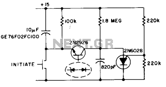
Description: This circuit functions as both an oscillator and a timer. The 2N6028 transistor remains in an 'on' state due to the excessive holding current flowing through the 100 kΩ resistor. When the switch is briefly closed, the 10 µF capacitor charges to a maximum of 15 volts, causing the 2N2926 transistor to initiate oscillation with capacitance values of 1.8 pF and 820 pF. The circuit maintains its state when the 2N2926 zener diode undergoes breakdown once more.
The described circuit utilizes a combination of transistors and passive components to achieve its dual functionality as an oscillator and a timer. The 2N6028, a silicon-controlled rectifier (SCR), is designed to remain conductive due to the continuous holding current provided by the 100 kΩ resistor. This configuration ensures that the SCR is kept in the 'on' state until a triggering event occurs.
Upon the momentary closure of the switch, the 10 µF capacitor begins to charge. The charging process raises the voltage across the capacitor to 15 volts, which is critical for the operation of the 2N2926 transistor. This transistor is configured to oscillate, and its oscillation frequency is influenced by the capacitances of 1.8 pF and 820 pF present in the circuit. These capacitive elements play a vital role in determining the timing characteristics and frequency of oscillation.
The oscillation of the 2N2926 is significant because it allows the circuit to produce a repetitive signal that can be utilized for various applications, such as generating clock pulses or controlling other electronic components. The feedback mechanism inherent in the design causes the circuit to latch when the zener diode within the 2N2926 breaks down. This breakdown condition reinforces the conduction state of the transistor, ensuring that the circuit remains active until it is intentionally reset or interrupted.
Overall, this circuit exemplifies the integration of transistors and passive components to create a versatile electronic device capable of functioning as both an oscillator and a timer, with specific operational characteristics dictated by the values of the resistors and capacitors used in the design.This circuit operates as an oscillator and a timer. The 2N6028 is normally on due to excess holding current through the 100 k resistor. When the switch is momentarily closed, the 10 µ¥ capacitor is charged to a full 15 volts and 2N2926 starts oscillating (1.8 and 820 pF). The circuit latches when 2N2926 zener breaks down again.
The described circuit utilizes a combination of transistors and passive components to achieve its dual functionality as an oscillator and a timer. The 2N6028, a silicon-controlled rectifier (SCR), is designed to remain conductive due to the continuous holding current provided by the 100 kΩ resistor. This configuration ensures that the SCR is kept in the 'on' state until a triggering event occurs.
Upon the momentary closure of the switch, the 10 µF capacitor begins to charge. The charging process raises the voltage across the capacitor to 15 volts, which is critical for the operation of the 2N2926 transistor. This transistor is configured to oscillate, and its oscillation frequency is influenced by the capacitances of 1.8 pF and 820 pF present in the circuit. These capacitive elements play a vital role in determining the timing characteristics and frequency of oscillation.
The oscillation of the 2N2926 is significant because it allows the circuit to produce a repetitive signal that can be utilized for various applications, such as generating clock pulses or controlling other electronic components. The feedback mechanism inherent in the design causes the circuit to latch when the zener diode within the 2N2926 breaks down. This breakdown condition reinforces the conduction state of the transistor, ensuring that the circuit remains active until it is intentionally reset or interrupted.
Overall, this circuit exemplifies the integration of transistors and passive components to create a versatile electronic device capable of functioning as both an oscillator and a timer, with specific operational characteristics dictated by the values of the resistors and capacitors used in the design.This circuit operates as an oscillator and a timer. The 2N6028 is normally on due to excess holding current through the 100 k resistor. When the switch is momentarily closed, the 10 µ¥ capacitor is charged to a full 15 volts and 2N2926 starts oscillating (1.8 and 820 pF). The circuit latches when 2N2926 zener breaks down again.
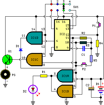
A Very Useful Timed Beeper Circuit
This circuit is designed for alerting purposes after a predetermined time has elapsed. It is ideal for tabletop games that require a fixed duration for answering questions or moving pieces. In this context, it serves as a modern alternative to...
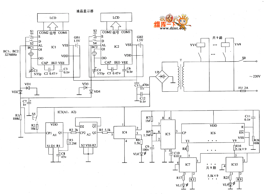
Automatic sprinkler controller circuit diagram 1
The automatic sprinkler controller circuit consists of a clock timing controller, a monostable flip-flop, a bistable flip-flop, an electronic switch, a self-excited multivibrator, a counter, a solenoid valve control circuit, and a power supply circuit. The power supply circuit includes...
A common collector amplifier
A common collector amplifier circuit structure and its key components are outlined. The composition of the common collector amplifier circuit is fundamentally similar to that of a common emitter amplifier circuit, with two notable exceptions: one is the collector resistor...
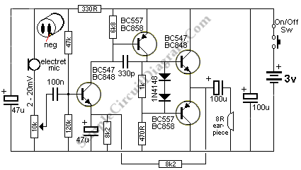
Small Amplifier Using Transistors
The output of this circuit is push-pull and consumes less than 3 mA (with no signal) but drives the earpiece to a very loud level when audio is detected.
This circuit operates in a push-pull configuration, which allows it to efficiently...
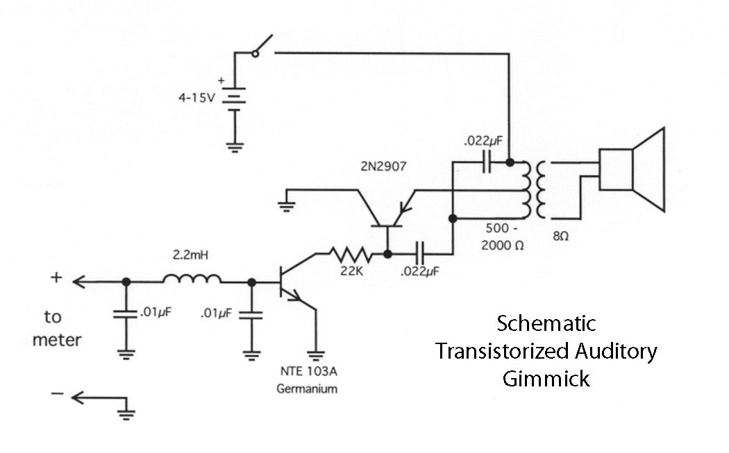
Transistorized Auditory Gimmick
This circuit first appeared in "The Braille Technical Press," edited by Robert W. Gunderson, in 1955. Gunderson, W2JIO, designed this "gimmick" to read transmitter meters. It has appeared many times over a 20-year period, including in commercial aids and appliances...
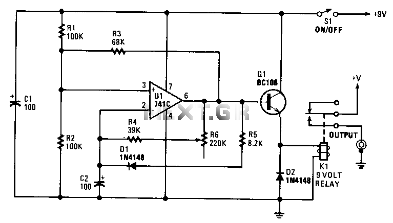
Slide-show-timer
The interval can be set between approximately 5 to 30 seconds. A relay controls the slide-change mechanism. Operational amplifier U1 functions as a type of Schmitt trigger. Resistors R1 and R2 bias the non-inverting input at pin 3 of U1...
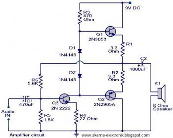
simple audio amplifier
The initial section of the circuit is a preamplifier that utilizes transistor Q1 (2N2222). The collector of transistor Q3 is connected to the base of transistor Q2 (2N2905A), which creates a complementary symmetry pair with Q3 (2N3053). The amplified signal...
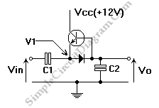
One Transistor Pump Building Block
This is a single transistor pump circuit. It is a straightforward circuit that is quite useful and can serve as a foundational component for designing more complex electronic systems.
The single transistor pump circuit utilizes a transistor as the primary active...
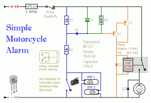
easy build motocycle alarm
The circuit requires two transistors to drive a relay, which acts as a switch to activate a buzzer. Any number of normally-open switches may be applied. Mercury switches should be installed to ensure they close when the steering is engaged....