


15hz zapper schematic
#15Hz
#zapper
#schematic
#frequency generator
#pulse generator
#electronic circuit
#component values
#signal generator
#low frequency
#waveform
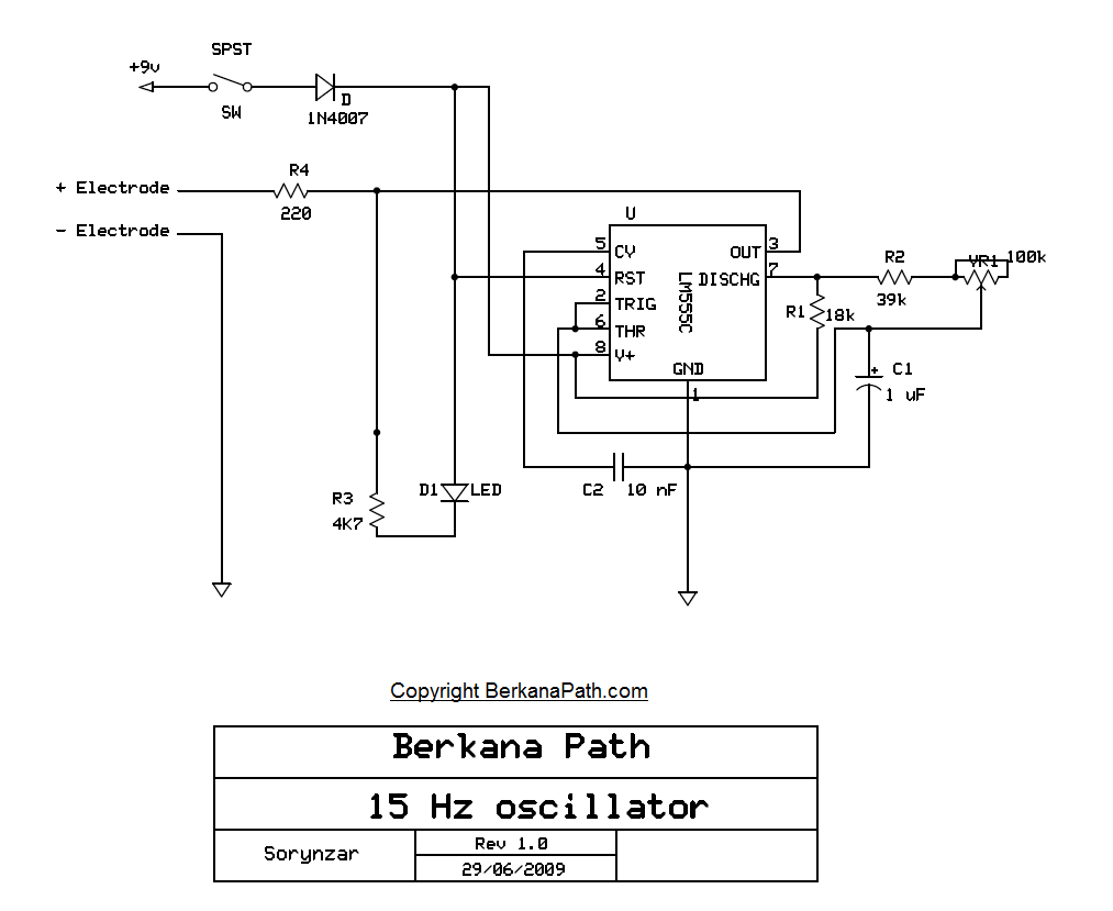
Description: A simple schematic detailing a 15Hz zapper with correct component values.
The schematic represents a 15Hz zapper circuit, which is designed to deliver electrical pulses at a frequency of 15 Hz. This type of device is often utilized for various therapeutic applications, including pain relief and muscle stimulation.
The circuit typically consists of several key components: a microcontroller or oscillator to generate the desired frequency, resistors to limit current, capacitors for timing and stability, and a transformer or output stage to deliver the pulses to the electrodes.
1. **Oscillator**: The oscillator is the heart of the circuit, generating a square wave output at 15 Hz. This can be achieved using a 555 timer IC configured in astable mode or a microcontroller programmed to produce the desired frequency.
2. **Resistors**: Resistors are used to set the timing characteristics of the oscillator and to limit the current flowing through the circuit. Proper selection of resistor values is crucial to ensure that the output signal remains within safe and effective limits.
3. **Capacitors**: Capacitors are employed to filter the output signal and stabilize the frequency. They also play a role in coupling the signal to the output stage, ensuring that the pulses are delivered effectively to the load.
4. **Output Stage**: The output stage may include a transformer or an operational amplifier configured to provide the necessary voltage and current levels to the electrodes. This stage is essential for ensuring that the pulses can penetrate the skin effectively and reach the target tissues.
5. **Electrodes**: The circuit interfaces with the user through electrodes, which are placed on the skin. The design should ensure that the electrodes are safe to use and provide good contact with the skin to facilitate effective treatment.
Overall, the design of a 15Hz zapper circuit requires careful consideration of component values and circuit topology to achieve the desired therapeutic effects while maintaining user safety. Proper testing and validation of the circuit are also essential to ensure reliability and effectiveness in its application.A simple schematic detailing a 15Hz zapper with correct component values..
The schematic represents a 15Hz zapper circuit, which is designed to deliver electrical pulses at a frequency of 15 Hz. This type of device is often utilized for various therapeutic applications, including pain relief and muscle stimulation.
The circuit typically consists of several key components: a microcontroller or oscillator to generate the desired frequency, resistors to limit current, capacitors for timing and stability, and a transformer or output stage to deliver the pulses to the electrodes.
1. **Oscillator**: The oscillator is the heart of the circuit, generating a square wave output at 15 Hz. This can be achieved using a 555 timer IC configured in astable mode or a microcontroller programmed to produce the desired frequency.
2. **Resistors**: Resistors are used to set the timing characteristics of the oscillator and to limit the current flowing through the circuit. Proper selection of resistor values is crucial to ensure that the output signal remains within safe and effective limits.
3. **Capacitors**: Capacitors are employed to filter the output signal and stabilize the frequency. They also play a role in coupling the signal to the output stage, ensuring that the pulses are delivered effectively to the load.
4. **Output Stage**: The output stage may include a transformer or an operational amplifier configured to provide the necessary voltage and current levels to the electrodes. This stage is essential for ensuring that the pulses can penetrate the skin effectively and reach the target tissues.
5. **Electrodes**: The circuit interfaces with the user through electrodes, which are placed on the skin. The design should ensure that the electrodes are safe to use and provide good contact with the skin to facilitate effective treatment.
Overall, the design of a 15Hz zapper circuit requires careful consideration of component values and circuit topology to achieve the desired therapeutic effects while maintaining user safety. Proper testing and validation of the circuit are also essential to ensure reliability and effectiveness in its application.A simple schematic detailing a 15Hz zapper with correct component values..
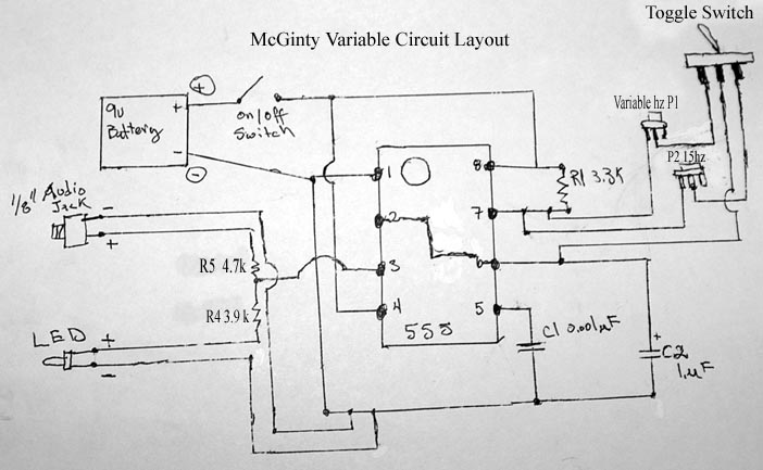
Frequency Generator:
Building your own Zapper. It requires one capacitor of 1 microfarad (C2), preferably unpolarized to eliminate concerns regarding positive and negative terminals. If a polarized capacitor is used, the longer leg indicates the positive side; refer to the schematic for...
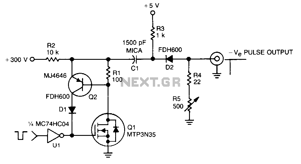
300V-pulse-generator
In this TMOS pulser, a negative-going pulse is applied to U1, a high-speed CMOS buffer, which directly drives the gate of Q1, an MTP3N35. If only a 100-V pulse is required, the MTA6N10 can be used. The pulse output across...
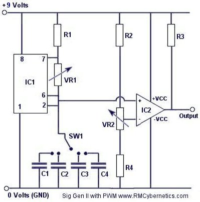
DIY Homemade Signal Generator with Pulse Width Modulation
Construct a signal generator using readily available components. It should produce a square wave with variable frequency and adjustable pulse width. This device can be utilized for various applications, including DC motor speed regulation, dimming of lamps or LEDs, transformer...
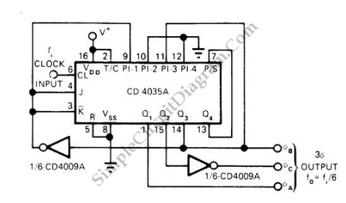
Pulse Generator Produces 3-Phase Output
This is a schematic diagram of a three-phase pulse generator circuit. This circuit produces a three-phase overlapped output similar to a three-phase AC power line.
The three-phase pulse generator circuit is designed to create three-phase output signals that are phase-shifted by...
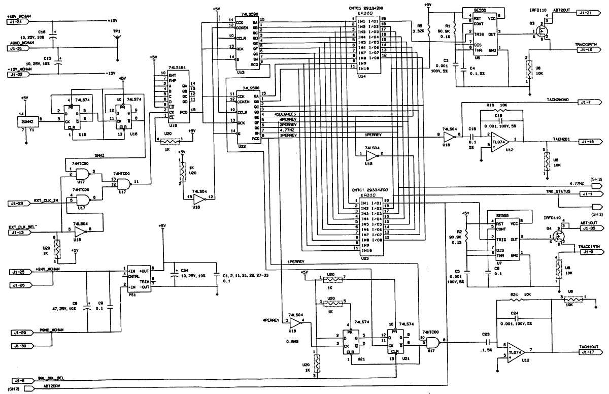
Signal Generator Electronic
This circuit illustrates a Signal Generator Electronic Circuit Diagram. Features: Unless otherwise specified, resistance values are in ohms.
The signal generator circuit is designed to produce various types of electrical signals, which can be sine, square, or triangular waves, depending on...
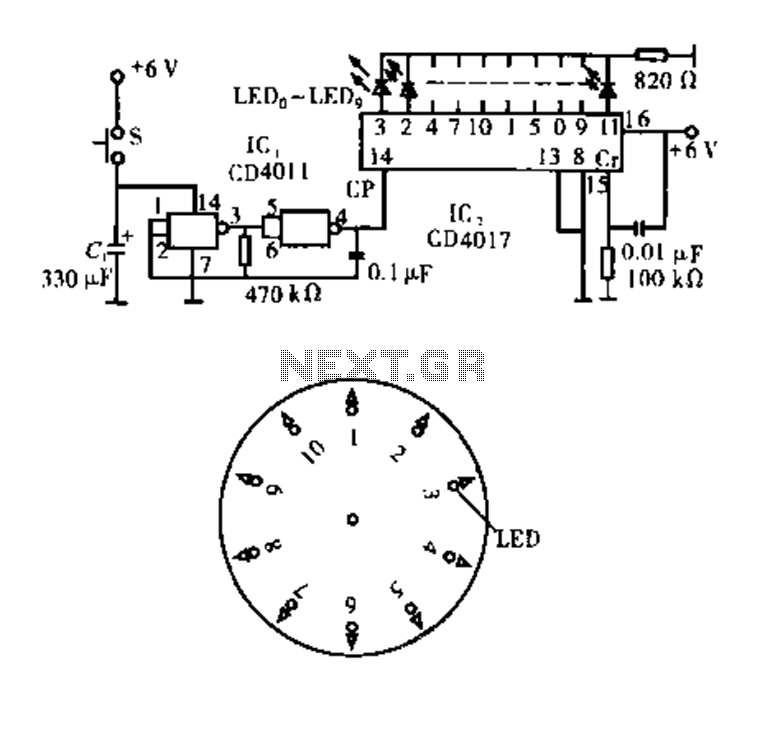
Electronic circuitry Dot Award
Dot Award. This circuit is tested and functional. The circuit consists of two integrated circuits (ICs). IC1 serves as a pulse source, activated by a momentary button switch (S). When the button is pressed, it charges capacitor C1, which powers...
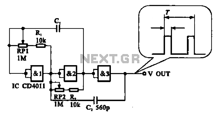
Adjustable pulse generator circuit
An adjustable pulse generator circuit is presented, which produces a periodic signal with independently adjustable pulse widths. The electrical path allows for modifications to the signal period through the adjustment of RP1. Additionally, RP2 can be altered to change the...
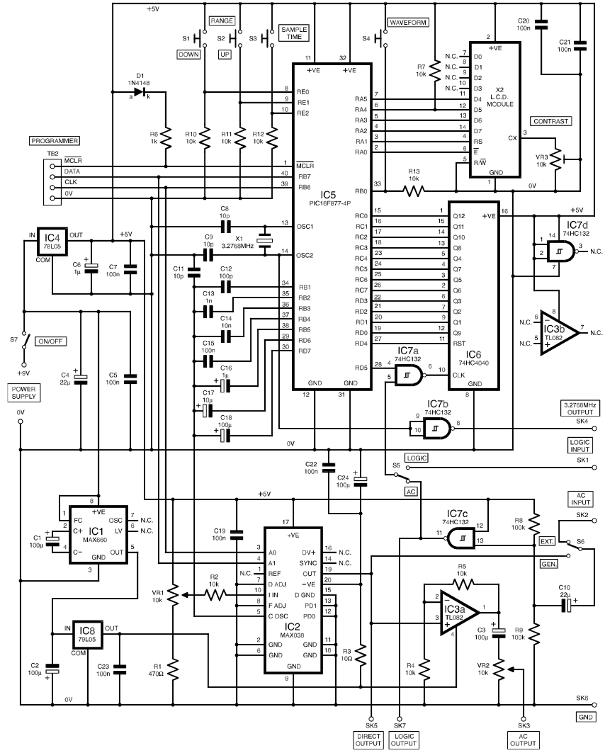
Frequency Generator Counter
The functional generator is a device that any well-equipped electronic lab should possess, even if it is not frequently used. However, its convenience is greatly appreciated when needed. This scheme was published in the magazine Everyday Practical Electronics, 2000, issue...
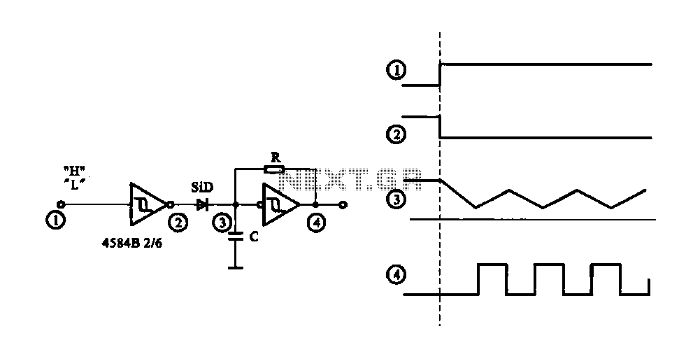
Controlled pulse signal generating circuit
The circuit generates a controlled pulse signal. When a high pulse signal is applied to the input terminal O (start), the output pulse signal is activated. Conversely, when a low signal is received at the input terminal O (stop), the...