


40kHZ ultrasonic transmitter circuit diagram
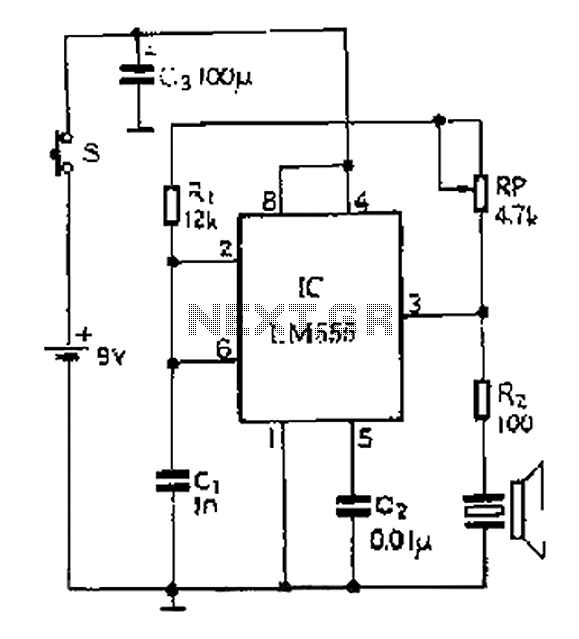
Description: A 40 kHz ultrasonic transmitter circuit utilizes the LM555 timer as a time base circuit along with external components to create a 40 kHz multivibrator. The resistance of the adjustable resistor RP can modify the oscillation frequency. The output from the LM555 drives an ultrasonic transducer (T40-16) to emit ultrasonic signals. This circuit is straightforward and operates with a voltage of 9V and a working current of 40 to 50 mA, capable of transmitting ultrasonic signals over distances greater than 8 meters. The LM555 timer can be replaced with the NE555, yielding the same performance.
The ultrasonic transmitter circuit operates at a frequency of 40 kHz, which is within the ultrasonic range, allowing for various applications such as distance measurement, object detection, and communication. The core of the circuit is the LM555 timer configured in astable mode to generate a continuous square wave output. The frequency of oscillation can be adjusted by varying the resistance of the potentiometer RP, which affects the timing capacitors and resistors in the circuit.
The LM555 output drives the ultrasonic transducer T40-16, which converts the electrical signals into ultrasonic sound waves. This transducer is specifically designed for ultrasonic applications, ensuring efficient conversion and transmission of the generated signals. The circuit is powered by a 9V supply, which is common for low-power electronic devices, ensuring ease of integration into various systems.
The current consumption of 40 to 50 mA indicates that the circuit is designed for low power applications, making it suitable for battery-operated devices. The ability to transmit ultrasonic signals over distances greater than 8 meters enhances its utility in various scenarios, such as in robotics for obstacle avoidance or in industrial applications for non-destructive testing.
In terms of component selection, the LM555 timer is a versatile and widely used component in timer, delay, pulse generation, and oscillator applications. The availability of the NE555 as a direct replacement ensures that the circuit can be easily maintained or modified without compromising performance. Overall, this ultrasonic transmitter circuit exemplifies simplicity and effectiveness in generating ultrasonic signals for a range of applications.40kHZ ultrasonic transmitter circuit of five, by the time base circuit LM555 and the external components 40kHZ multivibrator circuit, the resistance adjusting resistor RP can c hange the oscillation frequency. 3 feet from the LM555 output drives ultrasonic transducer T40-16, so as to emit ultrasonic signals. Circuit is simple and easy system. Circuit voltage of 9V, working current 40 ~ 50mA. Transmitting ultrasonic signals greater than 8m. LM555 NE555 direct replacement available, the effect is the same.
The ultrasonic transmitter circuit operates at a frequency of 40 kHz, which is within the ultrasonic range, allowing for various applications such as distance measurement, object detection, and communication. The core of the circuit is the LM555 timer configured in astable mode to generate a continuous square wave output. The frequency of oscillation can be adjusted by varying the resistance of the potentiometer RP, which affects the timing capacitors and resistors in the circuit.
The LM555 output drives the ultrasonic transducer T40-16, which converts the electrical signals into ultrasonic sound waves. This transducer is specifically designed for ultrasonic applications, ensuring efficient conversion and transmission of the generated signals. The circuit is powered by a 9V supply, which is common for low-power electronic devices, ensuring ease of integration into various systems.
The current consumption of 40 to 50 mA indicates that the circuit is designed for low power applications, making it suitable for battery-operated devices. The ability to transmit ultrasonic signals over distances greater than 8 meters enhances its utility in various scenarios, such as in robotics for obstacle avoidance or in industrial applications for non-destructive testing.
In terms of component selection, the LM555 timer is a versatile and widely used component in timer, delay, pulse generation, and oscillator applications. The availability of the NE555 as a direct replacement ensures that the circuit can be easily maintained or modified without compromising performance. Overall, this ultrasonic transmitter circuit exemplifies simplicity and effectiveness in generating ultrasonic signals for a range of applications.40kHZ ultrasonic transmitter circuit of five, by the time base circuit LM555 and the external components 40kHZ multivibrator circuit, the resistance adjusting resistor RP can c hange the oscillation frequency. 3 feet from the LM555 output drives ultrasonic transducer T40-16, so as to emit ultrasonic signals. Circuit is simple and easy system. Circuit voltage of 9V, working current 40 ~ 50mA. Transmitting ultrasonic signals greater than 8m. LM555 NE555 direct replacement available, the effect is the same.
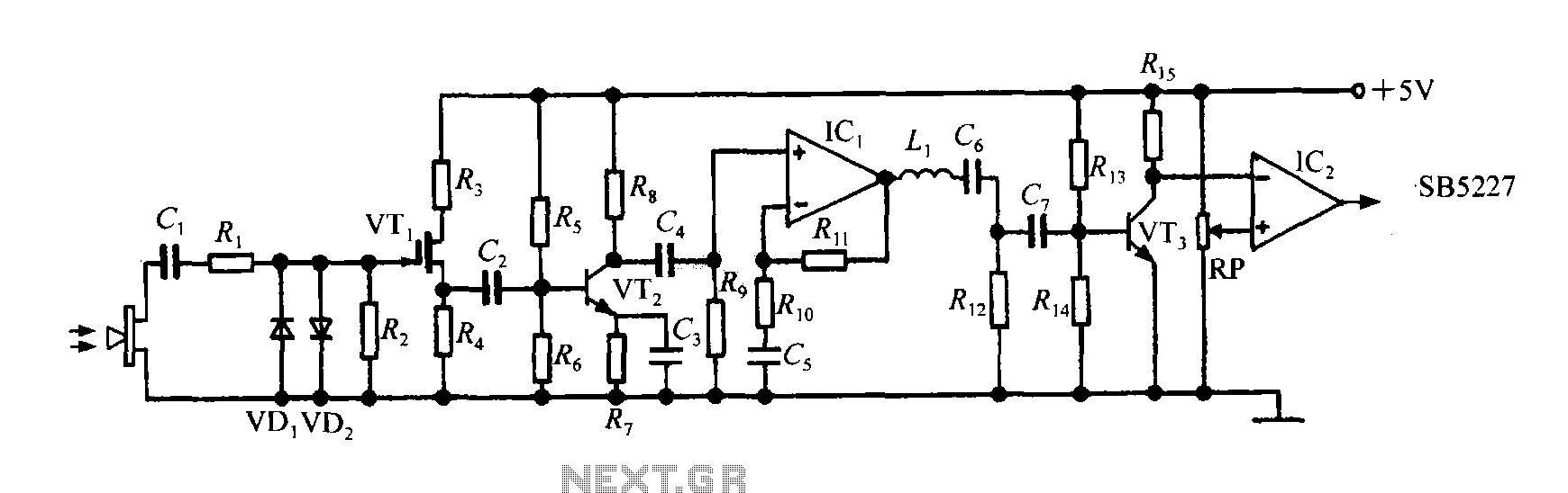
Intelligent ultrasonic ranging ASIC SB5227 peripheral circuit design
The SB5227 ultrasonic signal output is very weak and must be amplified via a power amplifier for effective transmission. A typical transmission circuit is illustrated in the accompanying figure. The SB5227 ultrasonic signal is sourced from output pin 10, which...
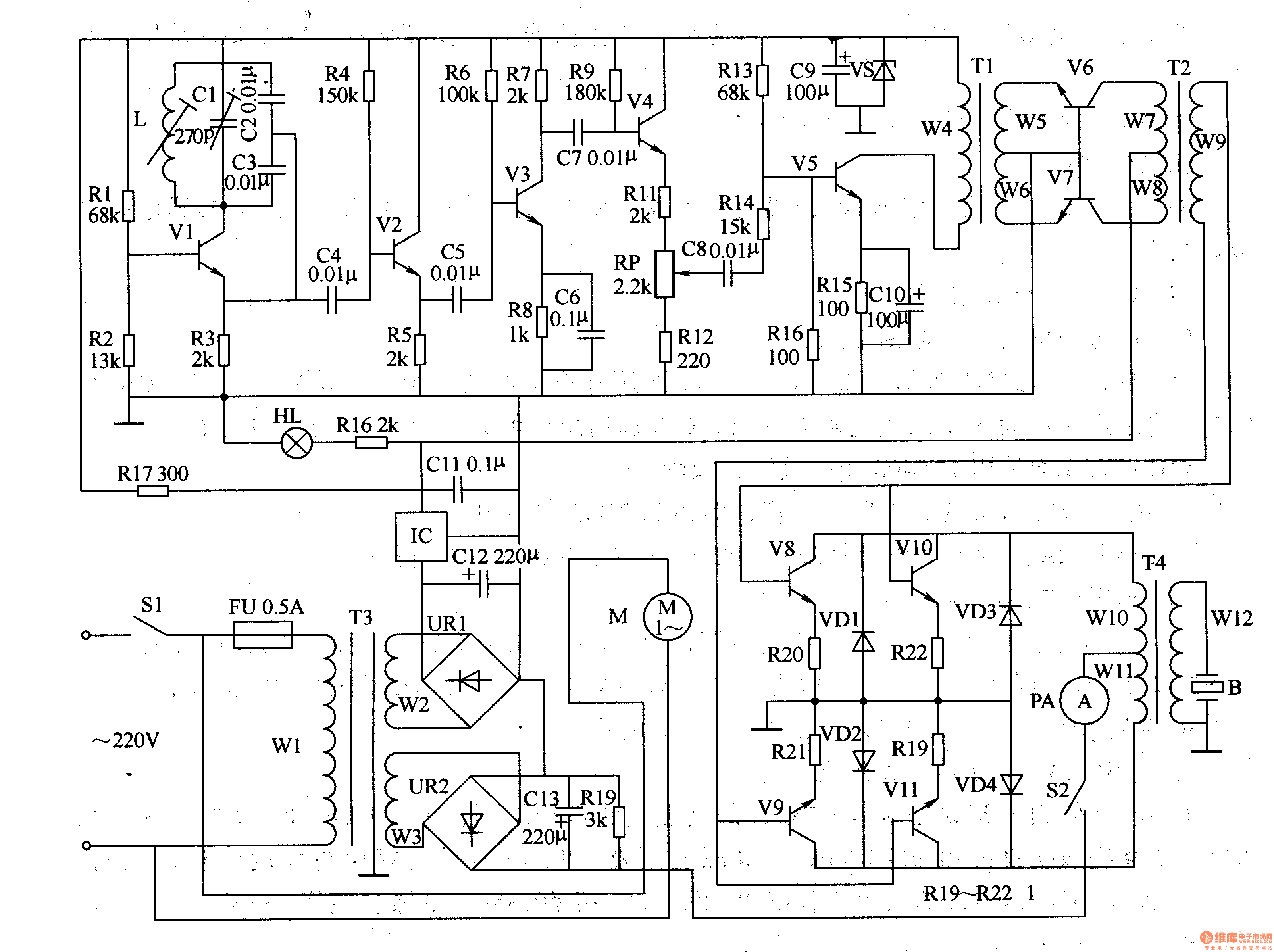
Ultrasonic Drilling Machine Two
The circuit comprises a power supply circuit, an ultrasonic oscillator circuit, a pre-amplifier, an amplifier, and a power amplifier drive output circuit. The power supply circuit includes a power switch (S1), a fuse (FU), a power transformer (T1), a bridge...
distance measuring sensor
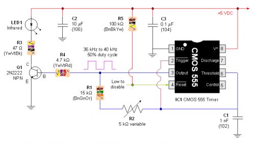
One basic method for distance measurement involves using an ultrasonic transducer. The principle is to send a burst of ultrasonic waves towards an object, which reflects the waves back to the ultrasonic receiver. By measuring the time delay between transmission...
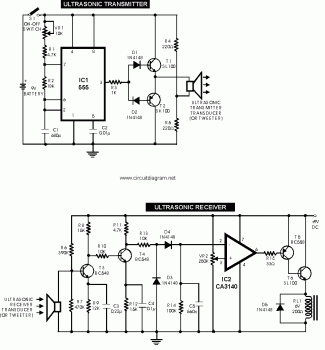
Ultrasonic Transmitter Sensor Switch circuit
This circuit explains alternate wireless switching using an ultrasonic sensor. The distance of the switching range should be more than 10 meters.
The described circuit employs an ultrasonic sensor to facilitate wireless switching, allowing for the activation or deactivation of devices...
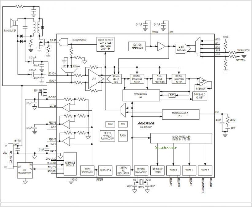
MAXQ7667 16-Bit RISC Microcontroller-Based Ultrasonic Distance-Measuring System
The MC33411 900 MHz Analog Cordless Phone Baseband system is designed to meet the specifications of a 900 MHz Analog cordless telephone system. It includes three Phase-Locked Loops (PLLs). Two of these PLLs are intended for use with external Voltage-Controlled...
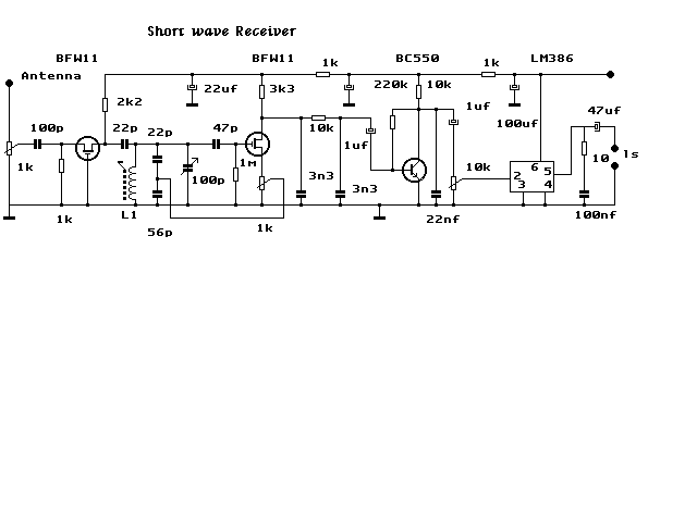
All Transmitter & Receiver schematics
This website was developed to assist students in discovering ideas for their projects or final year projects (FYP). All content presented here is sourced from reliable blogs, websites, and forums. The owner of this website assumes no responsibility for any...
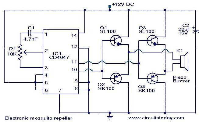
Electronic mosquito repeller
The circuit diagram of an ultrasonic mosquito repeller is based on the principle that insects, such as mosquitoes, can be repelled using sound frequencies in the ultrasonic range (above 20 kHz). The circuit utilizes a CMOS 4047 PLL IC configured...
Ultrasonic Mosquito Repeller Circuit Using CMOS IC
This is the design circuit diagram of an ultrasonic mosquito repeller. The circuit operates based on the theory that insects, such as mosquitoes, can be repelled by sound frequencies in the ultrasonic range (above 20 kHz). The circuit utilizes a...
Electronic Communication Projects
When the output of the multivibrator is low, Q1 (an NPN transistor) will be OFF and Q2 (a PNP transistor) will be ON. Consequently, the negative terminal of capacitor C3 will be connected to ground, allowing it to charge from...