


A variety of low-frequency waveform generator 741 circuit
#741
#waveform generator
#low-frequency
#triangle wave
#square wave
#operational amplifier
#signal generation
#analog circuit
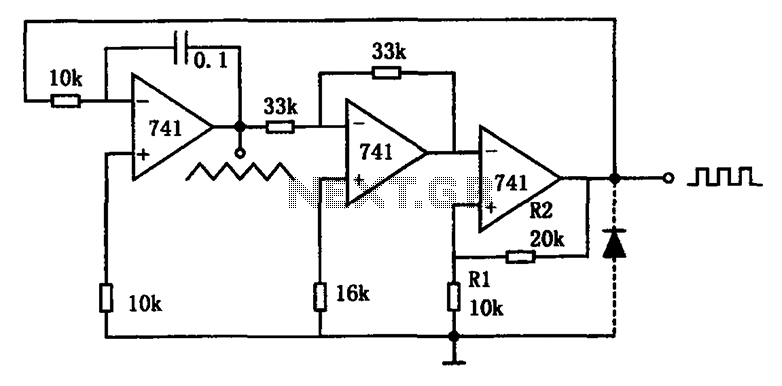
Description: The circuit illustrated generates a variety of low-frequency waveforms, specifically triangle and square waves, simultaneously. It consists of several stages: the first stage is an integrator, followed by a gain stage with an inverter, and a comparator stage that includes hysteresis. In the absence of a diode in the third stage, the circuit outputs a positive signal when the integrator produces a negative syncline wave, which is then inverted into a positive ramp for the comparator. When the ramp rate reaches the comparator's threshold level, defined as Vo = R1/(R1 + R2), the output switches to negative, leading the integrator to output a positive ramp. When the amplitude crosses a certain threshold, the circuit state changes, resulting in a triangle wave output from the first stage and a square wave output from the third stage, with a 180-degree phase difference between them. If a diode is added to the third stage, the clamping action results in a negative output of -0.7V from the comparator, producing sawtooth and pulse wave outputs. Regardless of the presence of the diode, the output frequency is determined by the time constant of the integrator and the voltage division ratio in the comparator, while the upper frequency limit of the circuit is 5 kHz.
The circuit operates by leveraging the properties of operational amplifiers configured in an integrator and comparator arrangement. The integrator stage converts input voltage into a ramp signal, which is then processed by the comparator to generate the desired output waveforms. The hysteresis in the comparator stage enhances stability by preventing rapid toggling between states, effectively filtering out noise that could lead to undesired waveform distortion.
In the triangle wave generation process, the integrator continuously ramps the voltage until it reaches the comparator's threshold. At this point, the comparator output toggles, causing the integrator to reverse its ramp direction. This behavior creates a linear increase and decrease in voltage, characteristic of triangle waves. The square wave is derived from the comparator output, which switches states at the same points that the triangle wave reaches its peak and trough.
In scenarios where a diode is incorporated into the output of the comparator, the circuit can produce sawtooth and pulse waveforms. The diode clamps the negative output, which modifies the waveform characteristics, resulting in a sharper transition between high and low states. The frequency of the output waveforms remains dependent on the time constant established by the resistor-capacitor (RC) network in the integrator stage, as well as the voltage division set by the resistors R1 and R2.
The operational amplifier's conversion rate is an important parameter, as it dictates the maximum frequency at which the circuit can reliably operate. With a limit of 5 kHz, the design is suitable for applications requiring low-frequency waveform generation, such as signal processing, waveform synthesis, and modulation tasks in various electronic systems. Overall, this circuit provides a versatile solution for generating essential waveforms in a compact and efficient manner. As shown in FIG variety of low-frequency waveform generating circuit. The circuit can simultaneously output two waveforms that triangle and square waves. Circuit, a first integ rator stage has a standard; a second gain stage inverter is 1; for the third stage of a comparator with hysteresis. In the third stage without diode, the circuit output is positive, the output of the integrator is negative syncline wave after wave inverted into a positive slant to the comparator.
When the ramp rate reached comparator threshold level Vo R1/(R1 + R2), the output is negative, then the integrator output is positive ramp; when the amplitude reaches a threshold level, and the circuit changes state, Thus, the first stage output triangle wave, square wave output of the third stage, the phase difference between them 180o. If the third-stage output plus one diode, since the clamping action of the diodes, the negative output of the comparator is -0.7V, then the circuit output sawtooth and pulse waves.
Whether plus access diode, the output frequency is determined by the time constant of the integrator, and a comparator supply voltage dividing ratio, its limit depends on the conversion rate of the operational amplifier. Limit frequency of the circuit is 5kHz.
The circuit operates by leveraging the properties of operational amplifiers configured in an integrator and comparator arrangement. The integrator stage converts input voltage into a ramp signal, which is then processed by the comparator to generate the desired output waveforms. The hysteresis in the comparator stage enhances stability by preventing rapid toggling between states, effectively filtering out noise that could lead to undesired waveform distortion.
In the triangle wave generation process, the integrator continuously ramps the voltage until it reaches the comparator's threshold. At this point, the comparator output toggles, causing the integrator to reverse its ramp direction. This behavior creates a linear increase and decrease in voltage, characteristic of triangle waves. The square wave is derived from the comparator output, which switches states at the same points that the triangle wave reaches its peak and trough.
In scenarios where a diode is incorporated into the output of the comparator, the circuit can produce sawtooth and pulse waveforms. The diode clamps the negative output, which modifies the waveform characteristics, resulting in a sharper transition between high and low states. The frequency of the output waveforms remains dependent on the time constant established by the resistor-capacitor (RC) network in the integrator stage, as well as the voltage division set by the resistors R1 and R2.
The operational amplifier's conversion rate is an important parameter, as it dictates the maximum frequency at which the circuit can reliably operate. With a limit of 5 kHz, the design is suitable for applications requiring low-frequency waveform generation, such as signal processing, waveform synthesis, and modulation tasks in various electronic systems. Overall, this circuit provides a versatile solution for generating essential waveforms in a compact and efficient manner. As shown in FIG variety of low-frequency waveform generating circuit. The circuit can simultaneously output two waveforms that triangle and square waves. Circuit, a first integ rator stage has a standard; a second gain stage inverter is 1; for the third stage of a comparator with hysteresis. In the third stage without diode, the circuit output is positive, the output of the integrator is negative syncline wave after wave inverted into a positive slant to the comparator.
When the ramp rate reached comparator threshold level Vo R1/(R1 + R2), the output is negative, then the integrator output is positive ramp; when the amplitude reaches a threshold level, and the circuit changes state, Thus, the first stage output triangle wave, square wave output of the third stage, the phase difference between them 180o. If the third-stage output plus one diode, since the clamping action of the diodes, the negative output of the comparator is -0.7V, then the circuit output sawtooth and pulse waves.
Whether plus access diode, the output frequency is determined by the time constant of the integrator, and a comparator supply voltage dividing ratio, its limit depends on the conversion rate of the operational amplifier. Limit frequency of the circuit is 5kHz.
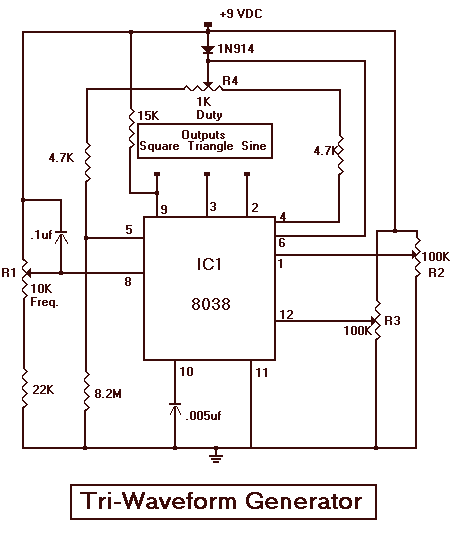
Triple Waveform Generator with 8038
The Tri-Waveform Generator can be used for a number of different uses. The one that I use it for is a signal generator to test circuits. The frequency range is 20 to 20kHz and can be adjusted by R1. The...
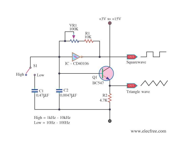
Triangle wave generator circuit with cmos inverter IC
This is a function generator project that can be used as a triangle and square wave generator. The main components include the CD40106, a popular CMOS integrated circuit, and a standard transistor.
The function generator circuit utilizes the CD40106, which is...
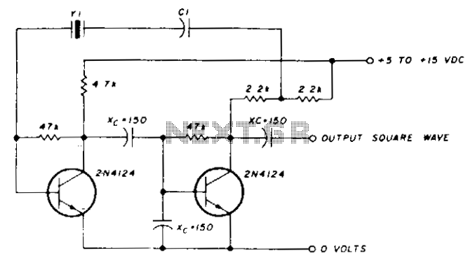
Low-frequency oscillator 10-150khz
A capacitor in series with the crystal may be utilized to adjust the oscillator output frequency. The value may range between 20 pF and 0.01 µF, or it may be a trimmer capacitor, and it will approximately equal the crystal...
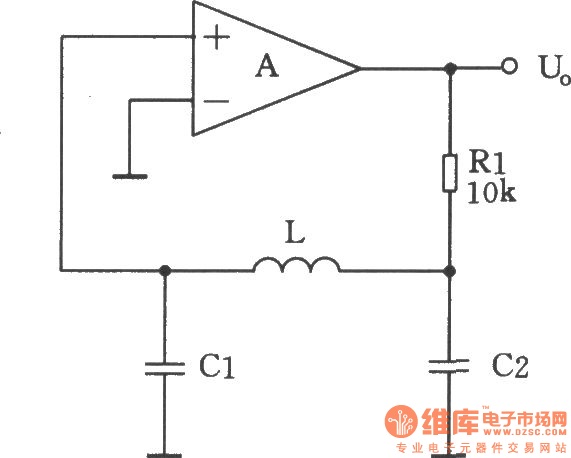
LC square wave generator
A square-wave generator utilizing an LC circuit can achieve improved frequency stability, as illustrated in the accompanying chart. This three-terminal capacitor oscillator is capable of generating a square wave, with an operational amplifier serving as the active component.
The square-wave generator...
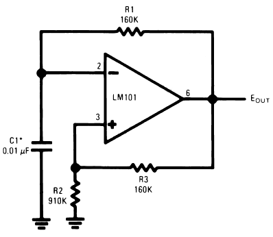
operational amplifier op amp oscillator
The timing capacitor (C1) generates multiple time constants, facilitating substantial voltage fluctuations at the input, attributable to the LM101's extensive input voltage range. It is advisable to decrease the value of resistor R2 and to increase the capacitance of C1...

LOW frequency square wave oscillator circuit
A simple circuit that can generate an inverted square wave similar to the one used by the inventor on his function generator.
To construct a circuit that produces an inverted square wave, a basic approach involves using a 555 timer IC...
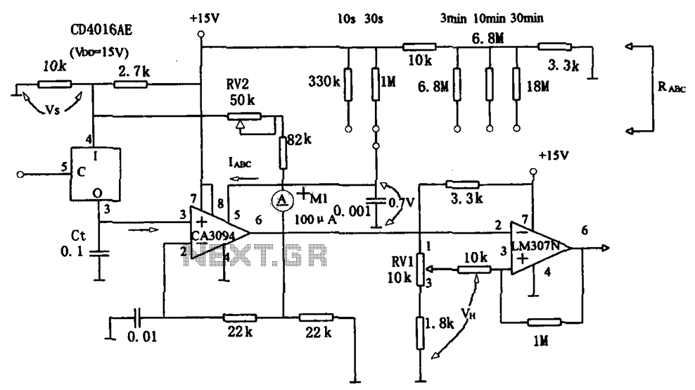
Long timed circuit diagram LM307N CA3094
The long timer circuit utilizes an operational amplifier, specifically the CA3094, to control the discharge formula for extended timing. This is typically achieved by adjusting the variable resistor RV1, which alters the timing duration to meet specific requirements.
The long timer...
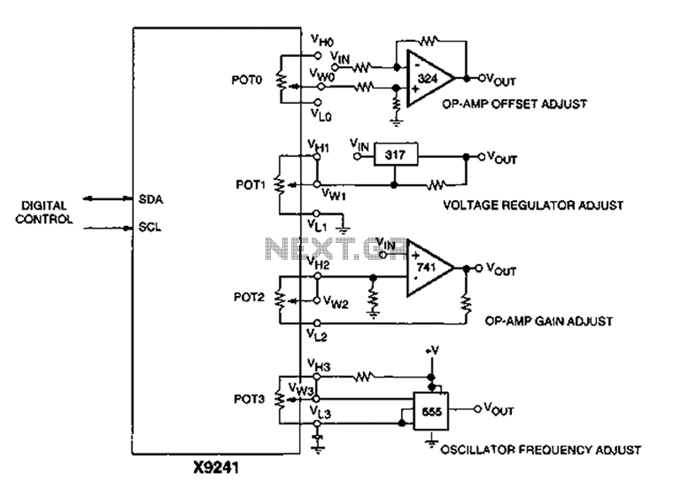
Corrector circuit diagram of an analog circuit
A XICOR X9241 POT IC module can be utilized to modify the four digital analog circuits, as depicted in the schematic.
The XICOR X9241 is a digital potentiometer integrated circuit designed for precise adjustment of analog signal levels in various electronic...
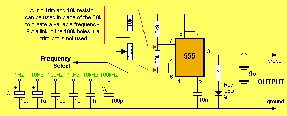
Square Wave Oscillator
Its most useful application is as a signal injector for radios and TVs. A square wave is the most suitable for testing the intermediate frequency (IF) strip as the signal will pass through the IF transformers without any attenuation, regardless...