


Accentuated beat metronome
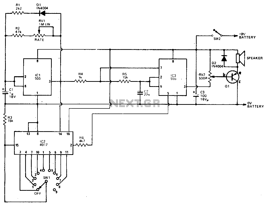
Description: IC3 functions as an oscillator that activates when the output of IC1 is high. The circuit generates two frequencies, approximately 800 Hz and 2500 Hz, based on the component values used. The output from IC3 is buffered by Q1, which drives the speaker. IC1 is responsible for generating the duration of the tone and the time intervals between beats. The interval can be adjusted using RV1, while the tone duration is determined by R1. Additionally, the output of IC1 provides a clock signal to IC2, which is a decade counter featuring 10 decoded outputs. Each output goes high in sequence with each clock pulse.
The second output of IC2 is connected to the control input of IC3, allowing for frequency modulation. Consequently, the first tone produced is at a high frequency, followed by a low frequency for the second tone, and the third to tenth tones revert to high frequency. This results in a 9-to-1 beat pattern. For instance, if the fifth output is linked to the reset function, the sequence will produce a high tone for the first, low for the second, high for the third and fourth, and upon the fifth output going high, the sequence resets back to the initial high tone. This configuration yields a pattern of three high tones followed by one low tone, or a 3-to-1 beat.
The oscillator IC3, which operates under the control of IC1, is critical for generating the audio tones utilized in the circuit. The frequencies produced are determined by the timing components associated with IC3, enabling the design to produce distinct audible signals that can be adjusted based on user preferences. The buffering stage provided by Q1 ensures that the speaker receives a clean and amplified signal, enhancing the sound output quality.
The decade counter IC2 plays a pivotal role in managing the sequence of tones. It effectively divides the input clock signal from IC1, generating a series of outputs that can be used to control the frequency and duration of the audio tones. The ability to connect the outputs of IC2 to other parts of the circuit, such as the reset function, allows for complex rhythmic patterns to be created, enhancing the versatility of the design. The adjustable components RV1 and R1 afford the user flexibility in customizing the beat intervals and tone lengths, making the circuit suitable for various applications including alarms, sound effects, or musical notes.
Overall, the integration of these components creates a robust and flexible audio generation system, capable of producing a variety of rhythmic patterns and sound frequencies based on user-defined parameters.IC3 acts as an oscillator which operates if the output of ICl is high. With the values used the two frequencies produced are about 800 Hz and 2500 Hz. The output is buffered by Ql which drives the speaker. The first IC is used to generate the tone duration and the time interval between beats. The interval is adjustable by RVl while the tone duration is set by Rl. The output of ICl also clocks IC2, a decade counter with 10 decoded outputs. Each of these outputs go high in sequence on each clock The second output of IC2 is connected to the control input of IC3 and is used to change the frequency. Therefore the first tone will be high frequency, the second low and the third to tenth will be high again.
This gives the 9-1 beat. If for example the 5th output is connected to the reset, the first tone will be high, the second low, and the third and fourth high, then when the 5th output goes to a high it resets it back to the first which is a high tone. We then have 3 high and one low tones or a 3-1.
The second output of IC2 is connected to the control input of IC3, allowing for frequency modulation. Consequently, the first tone produced is at a high frequency, followed by a low frequency for the second tone, and the third to tenth tones revert to high frequency. This results in a 9-to-1 beat pattern. For instance, if the fifth output is linked to the reset function, the sequence will produce a high tone for the first, low for the second, high for the third and fourth, and upon the fifth output going high, the sequence resets back to the initial high tone. This configuration yields a pattern of three high tones followed by one low tone, or a 3-to-1 beat.
The oscillator IC3, which operates under the control of IC1, is critical for generating the audio tones utilized in the circuit. The frequencies produced are determined by the timing components associated with IC3, enabling the design to produce distinct audible signals that can be adjusted based on user preferences. The buffering stage provided by Q1 ensures that the speaker receives a clean and amplified signal, enhancing the sound output quality.
The decade counter IC2 plays a pivotal role in managing the sequence of tones. It effectively divides the input clock signal from IC1, generating a series of outputs that can be used to control the frequency and duration of the audio tones. The ability to connect the outputs of IC2 to other parts of the circuit, such as the reset function, allows for complex rhythmic patterns to be created, enhancing the versatility of the design. The adjustable components RV1 and R1 afford the user flexibility in customizing the beat intervals and tone lengths, making the circuit suitable for various applications including alarms, sound effects, or musical notes.
Overall, the integration of these components creates a robust and flexible audio generation system, capable of producing a variety of rhythmic patterns and sound frequencies based on user-defined parameters.IC3 acts as an oscillator which operates if the output of ICl is high. With the values used the two frequencies produced are about 800 Hz and 2500 Hz. The output is buffered by Ql which drives the speaker. The first IC is used to generate the tone duration and the time interval between beats. The interval is adjustable by RVl while the tone duration is set by Rl. The output of ICl also clocks IC2, a decade counter with 10 decoded outputs. Each of these outputs go high in sequence on each clock The second output of IC2 is connected to the control input of IC3 and is used to change the frequency. Therefore the first tone will be high frequency, the second low and the third to tenth will be high again.
This gives the 9-1 beat. If for example the 5th output is connected to the reset, the first tone will be high, the second low, and the third and fourth high, then when the 5th output goes to a high it resets it back to the first which is a high tone. We then have 3 high and one low tones or a 3-1.
Jogging TimerCircuit
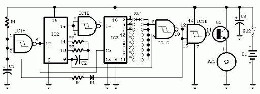
3V battery-powered circuit that emits a beep after a fixed delay of several minutes. This circuit was created in response to requests from users seeking a timer functionality.
The described circuit operates on a 3V power supply, making it suitable for...
Timer Circuit
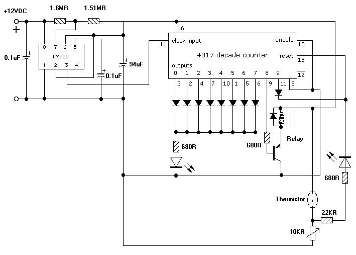
I am looking to build a timer for a pump. I want the pump to run for 5 minutes, then stop.
To create a timer circuit for a pump that operates for a duration of 5 minutes, a simple astable multivibrator...
Timer for Charger
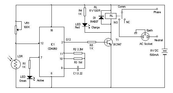
Timer for Charger Circuit Diagram. This timer circuit assists in maintaining the battery in optimal condition by enabling automatic charging for 5 to 6 hours daily, allowing the device to be left unattended.
The timer circuit for the charger is designed...
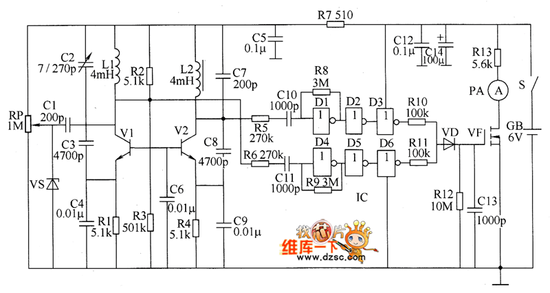
Metal detector circuit diagram 6
The metal detector circuit consists of several key components including the probe oscillator, reference oscillator, oscillation signal processor, mixing amplifier, and ammeter PA. The probe oscillator is made up of the oscillating tube VI, exploration coil L1, capacitors C1 to...

3V-30V/3A Adjustable Regulated Power Supply
This is an adjustable and regulated power supply with an output voltage range of 3V to 30V and a current supply capability of up to 3A. This circuit is equipped with short circuit protection and overload protection.
The adjustable power supply...
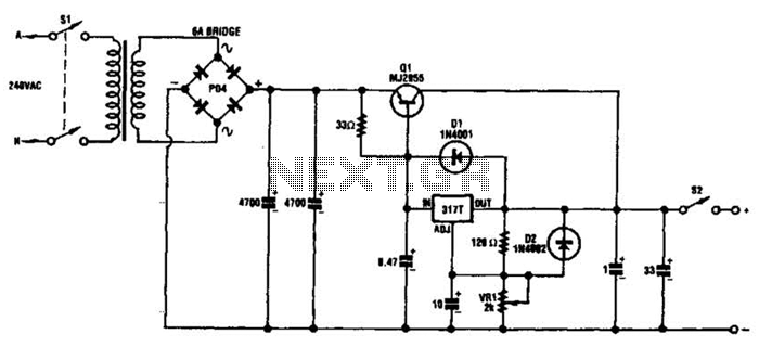
Adjustable 20V Supply Circuit
This circuit can deliver 3 A or more with a maximum DC voltage of slightly over 20 V. It is designed around the widely available LM317T adjustable 3-terminal regulator and incorporates a PNP power transistor to enhance the current output....
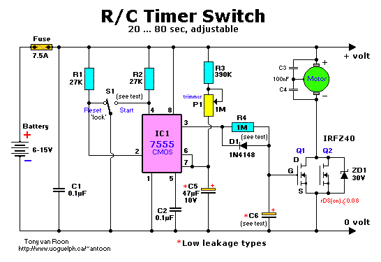
R/C Timer-Switch for Radio Control Applications
The project originated from a request by Tony Bowler, a member of the Long Eaton Club, who sought assistance in converting a "Golden Oldie" model to electric free-flight. He selected Vic Smeed's "Debutante" to be powered by seven AE size...
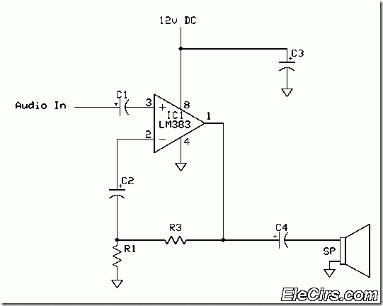
8 Watt Audio amplifier using LM383
The LM383 schematic represents an 8-watt audio amplifier, which is straightforward to construct as a mini-audio power amplifier. The parts list includes the following components: C1 - 1 unit of a 10µF electrolytic capacitor, C2 - 1 unit of a...
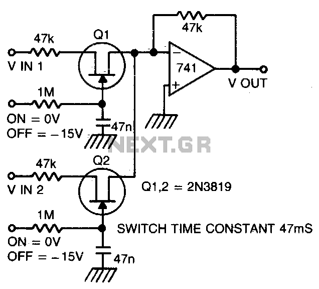
Silent audio switching-mixing
Two or more signals can be switched and/or mixed without annoying clicks by using FETs and a low input-impedance op amp circuit.
The circuit design utilizes Field Effect Transistors (FETs) to facilitate the switching and mixing of multiple signals while ensuring...