


Accurate 50Hz Oscillator Circuit Using 555 And 7490
#555 timer
#7490
#50Hz
#pulse generator
#frequency divider
#accurate timing
#digital counter
#signal generation
#clock circuit
#precision oscillator
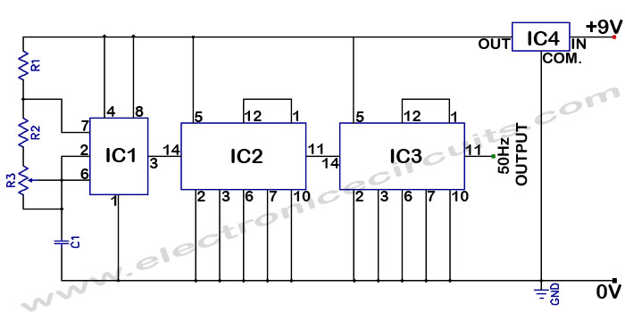
Description: Accurate 50Hz Oscillator Circuit Using 555 and 7490. This circuit generates a 50Hz pulse. It consists of a 555 timer and two 7490 divide-by-ten counters.
The circuit utilizes a 555 timer configured in astable mode to produce a square wave output. The frequency of oscillation is determined by the resistors and capacitors connected to the timer. Typically, standard values for resistors R1 and R2 and capacitor C1 are chosen to achieve the desired frequency of 50Hz.
The output from the 555 timer is fed into the first 7490 decade counter. This counter divides the frequency of the incoming pulse by ten. The output from the first 7490 is then connected to a second 7490 counter, which further divides the pulse by ten. The final output from the second 7490 will be a 50Hz signal, which is the desired frequency for this application.
The 555 timer's duty cycle can be adjusted by varying the resistor and capacitor values, allowing for flexibility in the pulse width. The 7490 counters are versatile and can be cascaded to achieve different division ratios, making this circuit adaptable for various frequency requirements.
Power supply considerations should also be noted; typically, a 5V to 15V DC supply is used for the 555 timer and 7490 counters. Proper decoupling capacitors are recommended near the power pins of the ICs to minimize noise and improve stability.
In summary, this circuit effectively generates a stable 50Hz pulse using a combination of a 555 timer and two 7490 decade counters, making it suitable for applications requiring precise timing signals.Accurate 50Hz Oscillator Circuit Using 555 And 7490 This circuit is a getting a 50Hz pulse. It comprises a 555 timer and two 7490 divide-by-ten..
The circuit utilizes a 555 timer configured in astable mode to produce a square wave output. The frequency of oscillation is determined by the resistors and capacitors connected to the timer. Typically, standard values for resistors R1 and R2 and capacitor C1 are chosen to achieve the desired frequency of 50Hz.
The output from the 555 timer is fed into the first 7490 decade counter. This counter divides the frequency of the incoming pulse by ten. The output from the first 7490 is then connected to a second 7490 counter, which further divides the pulse by ten. The final output from the second 7490 will be a 50Hz signal, which is the desired frequency for this application.
The 555 timer's duty cycle can be adjusted by varying the resistor and capacitor values, allowing for flexibility in the pulse width. The 7490 counters are versatile and can be cascaded to achieve different division ratios, making this circuit adaptable for various frequency requirements.
Power supply considerations should also be noted; typically, a 5V to 15V DC supply is used for the 555 timer and 7490 counters. Proper decoupling capacitors are recommended near the power pins of the ICs to minimize noise and improve stability.
In summary, this circuit effectively generates a stable 50Hz pulse using a combination of a 555 timer and two 7490 decade counters, making it suitable for applications requiring precise timing signals.Accurate 50Hz Oscillator Circuit Using 555 And 7490 This circuit is a getting a 50Hz pulse. It comprises a 555 timer and two 7490 divide-by-ten..
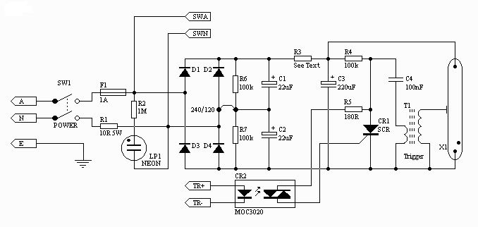
Xenon Strobe Light Circuit with IC555
The circuit was originally available in kit form from a surplus supplier, but it is likely more widely accessible now. It introduces innovative concepts such as utilizing a 555 timer as a pulse width modulator (PWM) and employing serial/parallel processing...
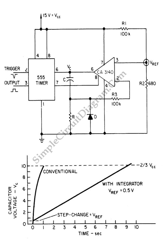
Extending 555 Timers Delay with Integrator
The 555 IC is a widely used component for timer circuits. By incorporating an integrator circuit, it is possible to extend the timing period of the 555 IC timer while maintaining a reasonable capacitor size.
The 555 timer IC is a...
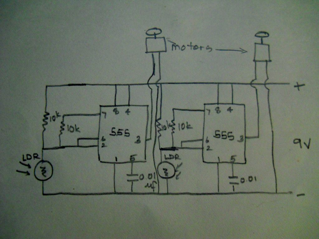
555 timer based light seeking robot
The schematic diagram of this robot is straightforward to comprehend. It is based on modifications made to a circuit from one of the reference books.
The schematic for the robot features a basic structure that integrates various electronic components to facilitate...
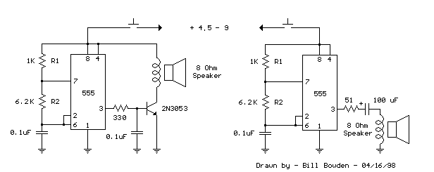
555 tone generator 8 ohm speaker
This is a basic 555 square wave oscillator designed to generate a 1 kHz tone for an 8-ohm speaker. In the circuit, the speaker is isolated from the oscillator by an NPN medium power transistor, which supplies more current than...
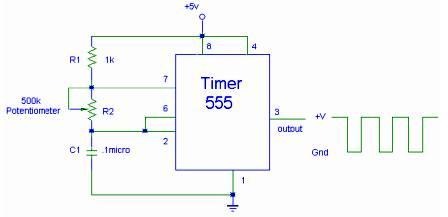
555 Timer IC for Square Wave Generator Application
The setup for the Square Wave Generator can be initiated using a 555 timer IC as illustrated in the accompanying circuit diagram. It is essential to reference the pinout configuration of the 555 timer IC. An oscilloscope should be connected...
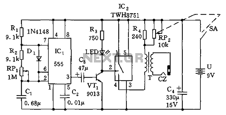
555 simple electronic circuit diagram massage
The circuit is composed of a 555 oscillator and an amplifier driver stage. It includes the 555 timer along with resistors R1, R2, RP1, capacitor C1, and other components forming a multi-harmonic oscillator. The frequency can be adjusted using RP1,...
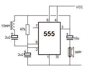
Metal detector using 555
A very simple metal detector electronic project can be designed using a simple 555 timer integrated circuit. As you can see in the schematic circuit, this electronic project requires few external electronic parts. This circuit detects metal and also magnets....
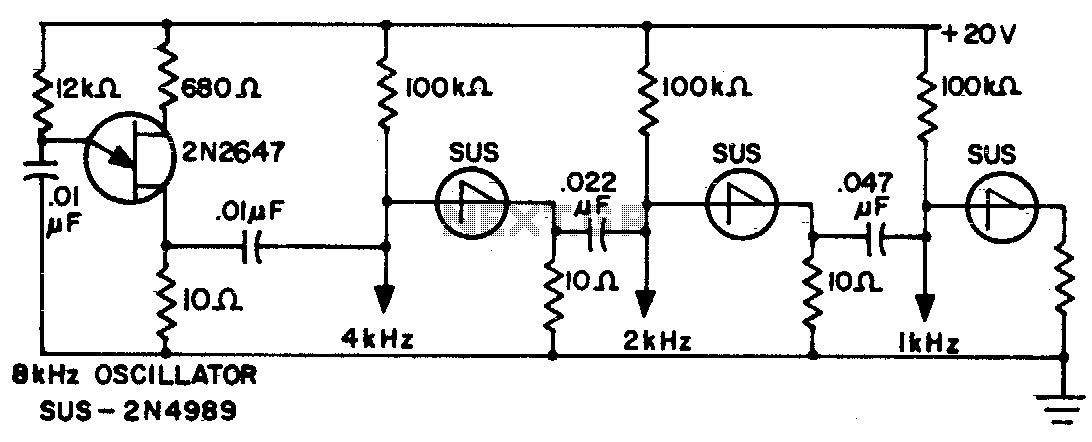
Frequency divider chain
The sawtooth output from each stage is one half the frequency of the preceding stage.
The described circuit features a multi-stage sawtooth waveform generator, where each stage produces an output with a frequency that is half of the frequency generated by...
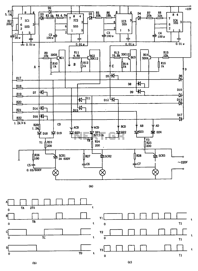
Advertising lights controller circuit diagram 555
The decorative lamp control circuit is illustrated in the figure. The controller comprises a pulse generator, a frequency divider, a matrix circuit, and a thyristor control circuit. Components IC1, R1, R2, C1, and others form a multivibrator where the oscillation...