


an132
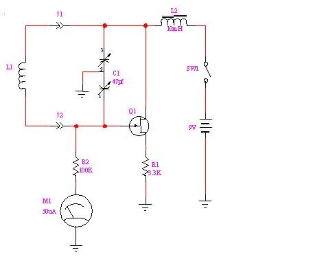
Description: The GDO initially utilized a triode vacuum tube configured as an oscillator, with a sensitive DC current meter measuring its grid current. Most contemporary versions are solid-state (JFET) and do not have a grid (or grid current), yet the name remains. This schematic illustrates an example of a GDO. In this circuit, L1 resonates with C1, generating oscillation. During operation, the RF energy in L1 couples into a tuned circuit under test. When the circuit under test absorbs energy from L1, the gate current in Q1 decreases, resulting in the needle on M1 dipping. L1 connects to the circuit because GDOs are supplied with a set of inductors to cover various frequency bands. A network analyzer typically lacks both a meter and an external coil for an oscillator. To operate the network analyzer like a GDO, the S11 port of the network analyzer is coupled to the circuit under test to observe a shift in the impedance level. As with any GDO, strong coupling between the instrument and the load is essential for a noticeable dip. A wire loop probe mounted to the end of a coaxial cable is employed to couple the network analyzer to the circuit under test. The precise design of the loop is contingent on the frequency range of interest. It is advisable to construct the loop with a characteristic impedance (Z) of 30 to 70 ohms for optimal results. Given that this application necessitates strong coupling, the shape factor of the loop is influenced by the physical properties of the circuit under test.
The GDO (Grid Dip Oscillator) serves as a vital tool in RF circuit testing and analysis. The original design, based on a triode vacuum tube, has evolved into modern solid-state implementations that utilize JFET technology. These contemporary versions retain the GDO nomenclature despite the absence of a grid, highlighting the device's historical significance.
In the provided schematic, L1 and C1 form a resonant circuit that produces oscillations at a specific frequency. The oscillation generated is critical for testing tuned circuits, as it allows for the measurement of energy absorption characteristics. When the circuit under test is connected, it interacts with the RF field produced by L1. This interaction is quantified by monitoring the gate current in Q1, which is indicative of the energy being absorbed. A decrease in gate current results in a corresponding dip in the meter reading (M1), providing a visual representation of the circuit's performance.
The GDO is equipped with various inductors, enabling it to operate across multiple frequency bands. This versatility is essential for RF engineers who require precise tuning capabilities for diverse applications. Unlike network analyzers, which are typically devoid of direct measurement capabilities for oscillation, the GDO's design allows for immediate feedback on circuit characteristics.
To adapt a network analyzer for GDO-like functionality, the S11 port must be effectively coupled to the circuit under test. This process involves careful impedance matching and the use of a wire loop probe, which is designed to facilitate strong coupling. The loop's design must consider the frequency range of interest, as it directly impacts the coupling efficiency. Achieving a characteristic impedance of 30 to 70 ohms is crucial for optimal performance, ensuring that the energy transfer between the network analyzer and the circuit under test is maximized.
The shape factor of the loop is also significant, as it must be tailored to the specific physical properties of the circuit being analyzed. This customization enables precise adjustments and enhances the accuracy of the measurements obtained. Overall, the GDO remains an indispensable instrument in the field of electronics, providing essential insights into the behavior of RF circuits.The GDO originally used a triode vacuum tube configured as an oscillator, with a sensitive DC current meter measuring its grid current. Most versions found today are solid state (JFET) and have no grid (or grid current), but the name has stuck.
This schematic shows an example of a GDO. In this circuit, L1 resonates with C1, creating an oscillation . In operation, the RF energy in L1 couples into a tuned circuit under test. When the circuit under test absorbs energy from L1, the gate current in Q1 drops, causing the needle on M1 to dip. L1 plugs into the circuit because GDOs come with a set of inductors to cover several bands of frequencies.
A network analyzer normally has neither a meter nor an external coil for an oscillator. To get the network analyzer to operate like a GDO, we try to couple the S11 port of the network analyzer to the circuit under test and look for a shift in the impedance level. As with any GDO, there must be a strong coupling between the instrument and the load to get a noticeable dip .
Use a wire loop probe mounted to the end of a coaxial cable to couple the network analyzer to the circuit under test. The exact design of the loop depends on the frequency range of interest. Try to make the loop with a Z of 30 to 70 ohms for best results. Since this application requires strong coupling, the shape factor of the loop depends on physical properties of the circuit under test.
The GDO (Grid Dip Oscillator) serves as a vital tool in RF circuit testing and analysis. The original design, based on a triode vacuum tube, has evolved into modern solid-state implementations that utilize JFET technology. These contemporary versions retain the GDO nomenclature despite the absence of a grid, highlighting the device's historical significance.
In the provided schematic, L1 and C1 form a resonant circuit that produces oscillations at a specific frequency. The oscillation generated is critical for testing tuned circuits, as it allows for the measurement of energy absorption characteristics. When the circuit under test is connected, it interacts with the RF field produced by L1. This interaction is quantified by monitoring the gate current in Q1, which is indicative of the energy being absorbed. A decrease in gate current results in a corresponding dip in the meter reading (M1), providing a visual representation of the circuit's performance.
The GDO is equipped with various inductors, enabling it to operate across multiple frequency bands. This versatility is essential for RF engineers who require precise tuning capabilities for diverse applications. Unlike network analyzers, which are typically devoid of direct measurement capabilities for oscillation, the GDO's design allows for immediate feedback on circuit characteristics.
To adapt a network analyzer for GDO-like functionality, the S11 port must be effectively coupled to the circuit under test. This process involves careful impedance matching and the use of a wire loop probe, which is designed to facilitate strong coupling. The loop's design must consider the frequency range of interest, as it directly impacts the coupling efficiency. Achieving a characteristic impedance of 30 to 70 ohms is crucial for optimal performance, ensuring that the energy transfer between the network analyzer and the circuit under test is maximized.
The shape factor of the loop is also significant, as it must be tailored to the specific physical properties of the circuit being analyzed. This customization enables precise adjustments and enhances the accuracy of the measurements obtained. Overall, the GDO remains an indispensable instrument in the field of electronics, providing essential insights into the behavior of RF circuits.The GDO originally used a triode vacuum tube configured as an oscillator, with a sensitive DC current meter measuring its grid current. Most versions found today are solid state (JFET) and have no grid (or grid current), but the name has stuck.
This schematic shows an example of a GDO. In this circuit, L1 resonates with C1, creating an oscillation . In operation, the RF energy in L1 couples into a tuned circuit under test. When the circuit under test absorbs energy from L1, the gate current in Q1 drops, causing the needle on M1 to dip. L1 plugs into the circuit because GDOs come with a set of inductors to cover several bands of frequencies.
A network analyzer normally has neither a meter nor an external coil for an oscillator. To get the network analyzer to operate like a GDO, we try to couple the S11 port of the network analyzer to the circuit under test and look for a shift in the impedance level. As with any GDO, there must be a strong coupling between the instrument and the load to get a noticeable dip .
Use a wire loop probe mounted to the end of a coaxial cable to couple the network analyzer to the circuit under test. The exact design of the loop depends on the frequency range of interest. Try to make the loop with a Z of 30 to 70 ohms for best results. Since this application requires strong coupling, the shape factor of the loop depends on physical properties of the circuit under test.
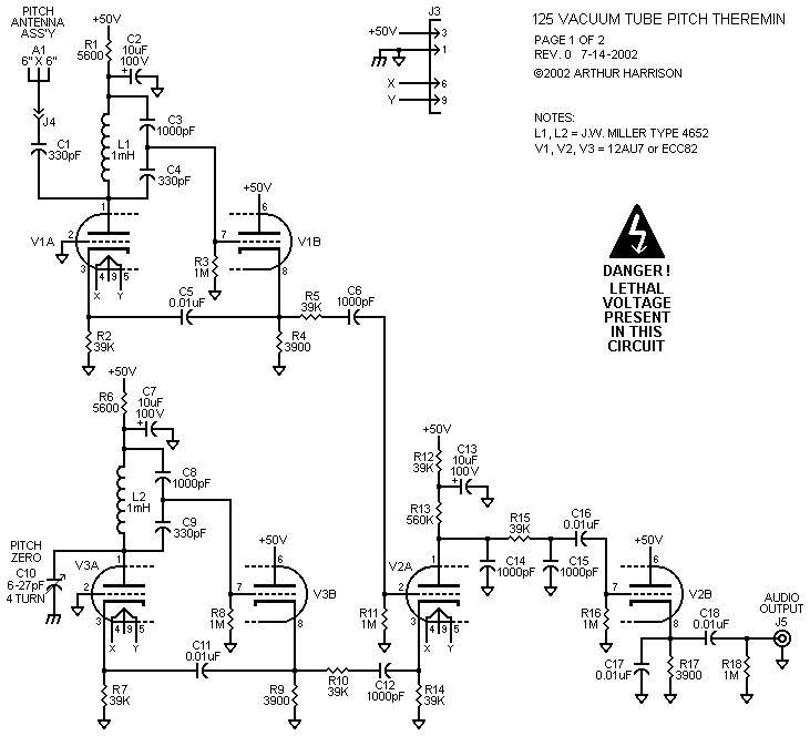
The 125 Vacuum Tube Pitch Theremin
The circuit operates using AC mains voltage and other high voltages that pose risks of injury or death. The 125 employs a basic heterodyne configuration, where the outputs of two similar radio-frequency Colpitts oscillators are fed into a mixer, generating...
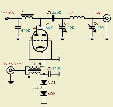
6N7 Tube QRP Power Amplifier
A powerful vacuum tube QRP amplifier designed for an 800mW QRPP homebrew telegraph vacuum tube transceiver named "3T." The decision to build this amplifier followed a period of using less than a watt of QRPP power for nearly a year....
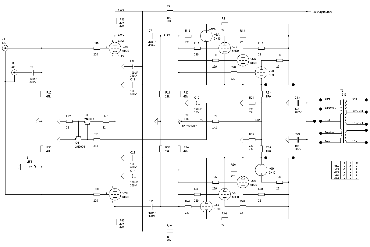
Cymbal Vacuum Tube Push/Pull Power Amplifier 6H30 6W
The Cymbal monoblock power amplifier features a modern push-pull design utilizing ultra-linear 6H30 triodes in a zero-feedback circuit. This unique configuration is optimized for sound quality rather than sheer power, making it ideal for efficient drivers and horn speakers. With...
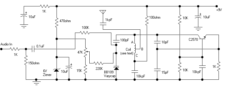
Colpitts oscillator FM transmitter
Its frequency depends on the capacitance of the vary cap diode. The center frequency is changed by varying the biasing voltage of the vary cap through the 47K pot. You can use a 75cm telescopic antenna or simply a length...
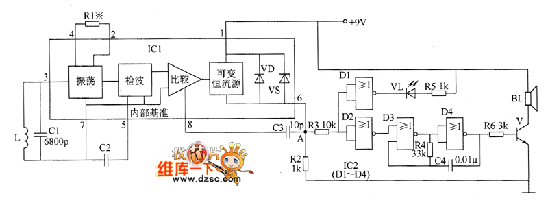
Metal detector circuit diagram 5
The metal detector circuit comprises an oscillator and a sound-light alarm circuit. The oscillator circuit includes an inductor (L), a capacitor (C1), a sensor switch integrated circuit (IC1) that integrates the oscillator, detector, comparator circuit, and peripheral components. The sound-light...
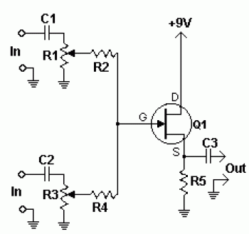
multi channel audio mixer using jfet
The 2N3819 is an n-channel JFET specifically designed for RF and mixer applications, offering very low noise, minimal distortion, and excellent high-frequency gain. Creating a PCB can be accomplished in a few straightforward steps. Begin by using PCB design software...
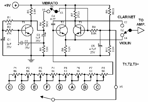
simple electronic organ
This electronic organ is simple to construct and can provide hours of enjoyment, particularly for children. The circuit is fundamentally an emitter-coupled oscillator consisting of transistors T2 and T3. A square wave voltage can be sampled from the collector of...
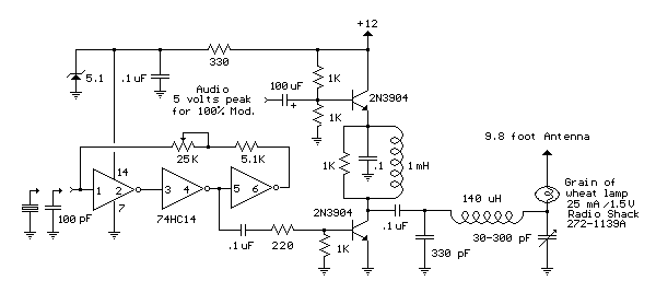
Micro Power AM Broadcast Transmitter
This circuit utilizes a 74HC14 hex Schmitt trigger inverter as a square wave oscillator to drive a small signal transistor configured in a class C amplifier setup. The frequency of the oscillator can be either fixed using a crystal or...
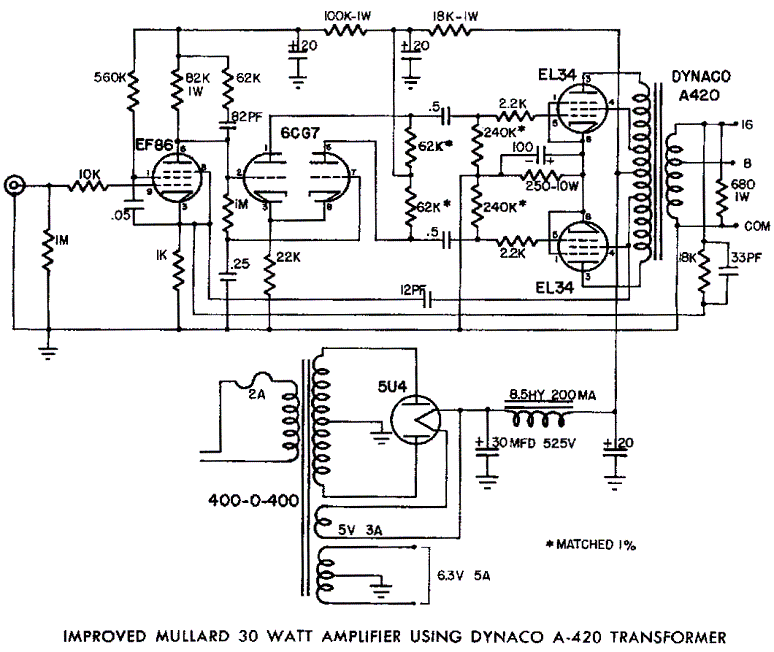
Mullard EL34 Push-Pull Tube Amp Schematic (Dynaco A420 Transformer)
Mullard EL34 push-pull vacuum tube amplifier schematic using Dynaco A420 audio output transformers
The Mullard EL34 push-pull vacuum tube amplifier is a classic audio amplification circuit that utilizes EL34 vacuum tubes in a push-pull configuration to deliver high-quality sound reproduction. This...