


Analysis of a Digitally Controlled Wien-Bridge Oscillator
#Wien-bridge oscillator
#JFET
#digital potentiometer
#digipot
#stability
#flexibility
#frequency control
#analog circuits
#signal generation
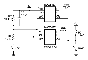
Description: This application note analyzes the details of a Wien-bridge oscillator, shows how a JFET maintains oscillation, and demonstrates adding a digital potentiometer (digipot), rather than a variable resistor, to improve stability and flexibility.
The Wien-bridge oscillator is a type of electronic oscillator that generates sine waves. It utilizes a bridge circuit that consists of resistors and capacitors to establish the necessary phase shift for oscillation. The fundamental operational principle of the Wien-bridge oscillator is based on the balance of impedances in the bridge circuit, which allows for the generation of a stable frequency output.
A key component of the Wien-bridge oscillator is the use of a JFET (Junction Field-Effect Transistor), which acts as a gain element. The JFET is essential for maintaining oscillation by providing the necessary gain to overcome losses in the circuit. Its high input impedance and low noise characteristics make it an ideal choice for this application. The gain of the JFET can be controlled dynamically, allowing for automatic adjustment of the oscillation amplitude.
Incorporating a digital potentiometer (digipot) instead of a traditional variable resistor offers several advantages. The digipot allows for precise control over resistance values through digital signals, which enhances the stability of the oscillator. This digital control enables fine-tuning of the oscillation frequency and amplitude without the mechanical wear and variability associated with analog potentiometers. Additionally, the integration of a microcontroller can facilitate automated adjustments based on real-time feedback, further improving the performance and reliability of the oscillator circuit.
Overall, the combination of a Wien-bridge oscillator with a JFET and a digital potentiometer represents a modern approach to generating stable sine wave signals suitable for various applications, including signal processing, waveform generation, and audio applications. The flexibility and precision offered by this configuration make it a valuable tool in the field of electronics.This application note analyzes the details of a Wien-bridge oscillator, shows how a JFET maintains oscillation, and demonstrates adding a digital potentiometer (digipot), rather than a variable resistor, to improve stability and flexibility..
The Wien-bridge oscillator is a type of electronic oscillator that generates sine waves. It utilizes a bridge circuit that consists of resistors and capacitors to establish the necessary phase shift for oscillation. The fundamental operational principle of the Wien-bridge oscillator is based on the balance of impedances in the bridge circuit, which allows for the generation of a stable frequency output.
A key component of the Wien-bridge oscillator is the use of a JFET (Junction Field-Effect Transistor), which acts as a gain element. The JFET is essential for maintaining oscillation by providing the necessary gain to overcome losses in the circuit. Its high input impedance and low noise characteristics make it an ideal choice for this application. The gain of the JFET can be controlled dynamically, allowing for automatic adjustment of the oscillation amplitude.
Incorporating a digital potentiometer (digipot) instead of a traditional variable resistor offers several advantages. The digipot allows for precise control over resistance values through digital signals, which enhances the stability of the oscillator. This digital control enables fine-tuning of the oscillation frequency and amplitude without the mechanical wear and variability associated with analog potentiometers. Additionally, the integration of a microcontroller can facilitate automated adjustments based on real-time feedback, further improving the performance and reliability of the oscillator circuit.
Overall, the combination of a Wien-bridge oscillator with a JFET and a digital potentiometer represents a modern approach to generating stable sine wave signals suitable for various applications, including signal processing, waveform generation, and audio applications. The flexibility and precision offered by this configuration make it a valuable tool in the field of electronics.This application note analyzes the details of a Wien-bridge oscillator, shows how a JFET maintains oscillation, and demonstrates adding a digital potentiometer (digipot), rather than a variable resistor, to improve stability and flexibility..
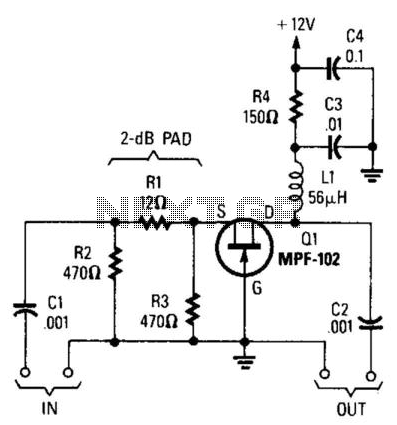
Jfet Wideband Amplifier
Using an MPF102 JFET, this circuit has a 50-ohm input impedance. The load impedance should be approximately 470 ohms. A 3:1 matching transformer can be utilized to return the impedance to 50 ohms. This circuit will exhibit a gain of...
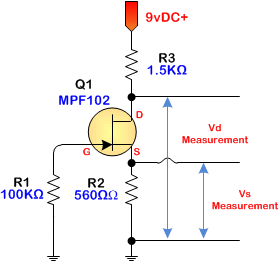
JFET iPod preamplifier
JFET iPod preamplifier, DIY Hi-Fi, schematic
The JFET iPod preamplifier circuit is designed to amplify the audio signal from an iPod or similar portable audio device, enabling it to drive higher impedance loads such as amplifiers or speakers. This circuit typically...
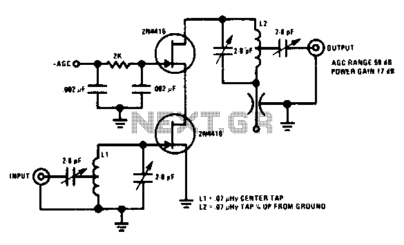
200Mhz cascode amplifier
This 200 MHz JFET cascode circuit features low cross-modulation, large signal handling ability, no neutralization, and automatic gain control (AGC) managed by biasing the upper cascode JFET. The only special requirement of this circuit is that the drain-source saturation current...
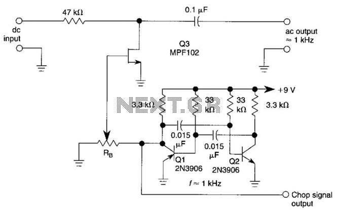
Jfet Chopper Circuit Circuit
A JFET (MPF102) is utilized to chop a DC signal for amplification in an AC-coupled amplifier. Q3 serves as the chopper element, while Q1 and Q2 create a multivibrator to generate the chopping signal. Additionally, resistor Rr establishes the bias...
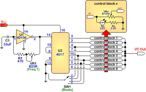
project armageddon processor
This circuit is a simple JFET input buffer that connects to a clean boost inspired by the Electro-Harmonix LPB-1 Linear Power Boost. The guitar input is buffered and then split into four input points, allowing connections to various other modules....
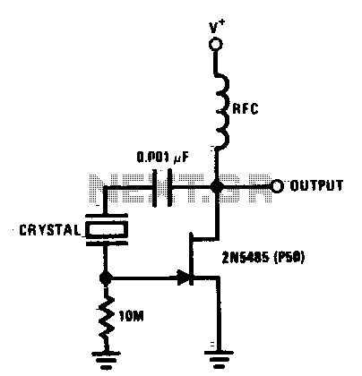
Jfet pierce crystal oscillator
The JFET Pierce crystal oscillator accommodates a broad frequency range of crystals without requiring circuit modifications. The JFET gate does not load the crystal, which preserves a high quality factor (Q) and ensures excellent frequency stability.
The JFET Pierce oscillator is...
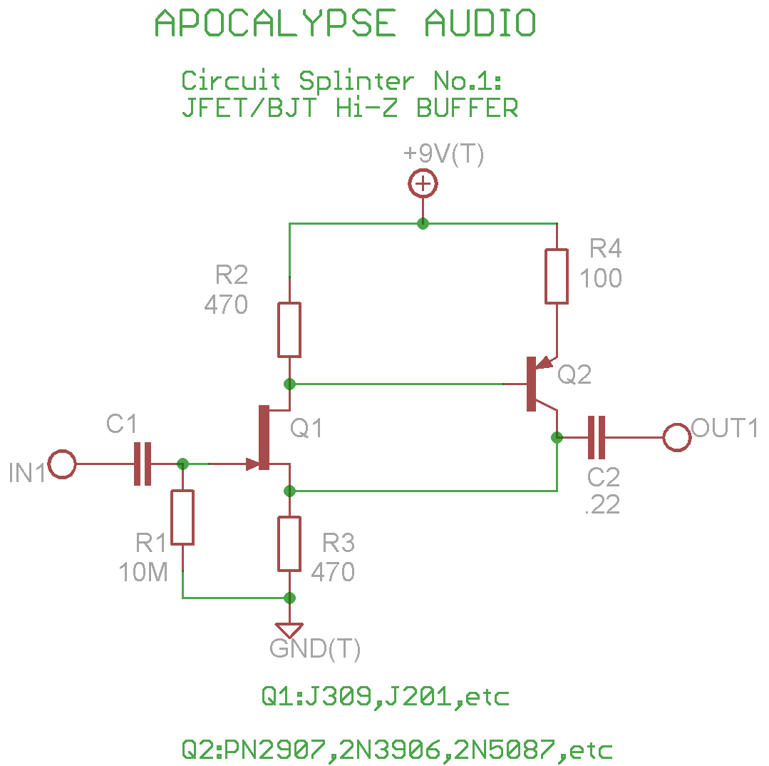
high impedance input JFET/BJT buffer circuit
This is a common circuit often found in various resources, yet it appears to be less prevalent in stompbox applications. The circuit utilizes an NPN JFET DC coupled with a PNP BJT. The FET provides a significantly higher input impedance...
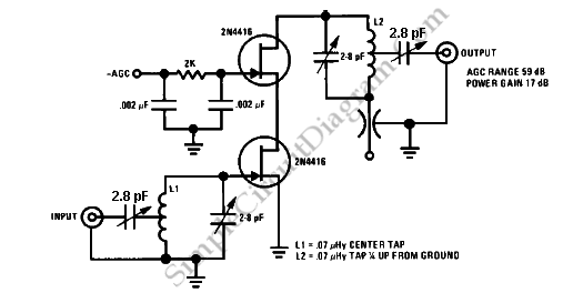
200 MHz Cascade Amplifier
The 200 MHz JFET possesses the following characteristics: 1. Low crossmodulation 2. High large-signal handling capability 3. No requirement for neutralization 4. Automatic Gain Control (AGC) managed by adjusting the biasing of the upper.
The 200 MHz Junction Field Effect Transistor...
200 MHz Cascade Amplifier
The 200 MHz JFET possesses the following characteristics: 1. Low crossmodulation 2. High large-signal handling capability 3. No requirement for neutralization 4. Automatic Gain Control (AGC) managed by adjusting the biasing of the upper.
The 200 MHz Junction Field Effect Transistor...