


capacitor Whats wrong with this Phase Shift Oscillator
#phase shift oscillator
#CE amplifier
#oscillation frequency
#capacitor
#gain
#1.5 kHz
#transistor
#feedback
#signal generator
#RC network
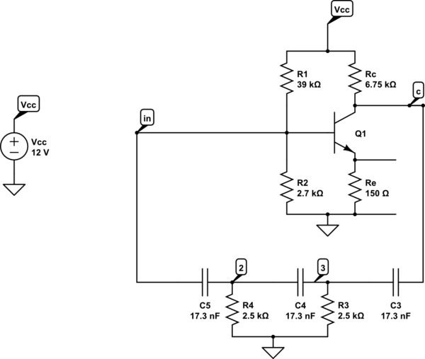
Description: A phase shift oscillator utilizing a common emitter (CE) amplifier. The circuit operates with a collector voltage (Vc) of approximately 6V and achieves a gain of around 40, exceeding the minimum requirement of 29. The target oscillation frequency is set at 1.5 kHz.
The phase shift oscillator is a type of electronic oscillator that generates a sine wave output by utilizing the phase shift provided by passive components in conjunction with an active amplifier. In this configuration, a common emitter amplifier is employed, which provides the necessary gain and phase shift to sustain oscillations.
The circuit typically consists of three RC (resistor-capacitor) stages, each contributing a phase shift of 60 degrees, totaling a 180-degree phase shift. This phase shift is complemented by an additional 180-degree phase shift provided by the common emitter amplifier, resulting in a total phase shift of 360 degrees, which is essential for oscillation.
Key components include:
1. **Common Emitter Amplifier**: The transistor operates in the active region, providing voltage gain. The collector voltage (Vc) is set to approximately 6V, which is optimal for the transistor's operation and ensures sufficient headroom for the output signal.
2. **Resistors and Capacitors**: The values of the resistors and capacitors in the RC network are chosen to set the desired oscillation frequency of 1.5 kHz. The frequency can be calculated using the formula:
\[
f = \frac{1}{2\pi R_{total}C_{total}}
\]
where \(R_{total}\) is the equivalent resistance of the resistors in the network and \(C_{total}\) is the total capacitance.
3. **Feedback Loop**: The output of the amplifier is fed back to the input through the RC network, which ensures that the oscillation condition is met. The gain of the amplifier must be greater than 29 to maintain oscillations, and in this design, it is set to approximately 40, providing a robust margin for stability.
4. **Power Supply**: The circuit requires a suitable DC power supply to provide the necessary voltage for the amplifier. The choice of components must account for the power supply voltage to ensure proper operation without distortion of the output waveform.
In summary, this phase shift oscillator design effectively combines the common emitter amplifier with a carefully calculated RC network to achieve stable oscillations at the desired frequency of 1.5 kHz, with adequate gain and phase conditions met for sustained operation.A phase shift oscillator, using a CE Amplifier. I have a Vc of approximately 6V, gain of approximately 40(>29, as required). I aim for an oscillation frequency of 1. 5 kHz.
The phase shift oscillator is a type of electronic oscillator that generates a sine wave output by utilizing the phase shift provided by passive components in conjunction with an active amplifier. In this configuration, a common emitter amplifier is employed, which provides the necessary gain and phase shift to sustain oscillations.
The circuit typically consists of three RC (resistor-capacitor) stages, each contributing a phase shift of 60 degrees, totaling a 180-degree phase shift. This phase shift is complemented by an additional 180-degree phase shift provided by the common emitter amplifier, resulting in a total phase shift of 360 degrees, which is essential for oscillation.
Key components include:
1. **Common Emitter Amplifier**: The transistor operates in the active region, providing voltage gain. The collector voltage (Vc) is set to approximately 6V, which is optimal for the transistor's operation and ensures sufficient headroom for the output signal.
2. **Resistors and Capacitors**: The values of the resistors and capacitors in the RC network are chosen to set the desired oscillation frequency of 1.5 kHz. The frequency can be calculated using the formula:
\[
f = \frac{1}{2\pi R_{total}C_{total}}
\]
where \(R_{total}\) is the equivalent resistance of the resistors in the network and \(C_{total}\) is the total capacitance.
3. **Feedback Loop**: The output of the amplifier is fed back to the input through the RC network, which ensures that the oscillation condition is met. The gain of the amplifier must be greater than 29 to maintain oscillations, and in this design, it is set to approximately 40, providing a robust margin for stability.
4. **Power Supply**: The circuit requires a suitable DC power supply to provide the necessary voltage for the amplifier. The choice of components must account for the power supply voltage to ensure proper operation without distortion of the output waveform.
In summary, this phase shift oscillator design effectively combines the common emitter amplifier with a carefully calculated RC network to achieve stable oscillations at the desired frequency of 1.5 kHz, with adequate gain and phase conditions met for sustained operation.A phase shift oscillator, using a CE Amplifier. I have a Vc of approximately 6V, gain of approximately 40(>29, as required). I aim for an oscillation frequency of 1. 5 kHz.
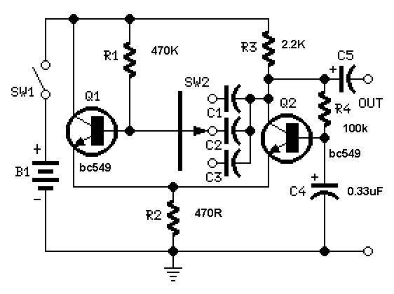
Simple Square wave Generator using transistors ~ Easy Electronics
A useful feature of this circuit is that the frequency can be changed by modifying the capacitor value. A switch can be added to select between various frequencies.
This circuit utilizes a capacitor in conjunction with an oscillator to determine its...
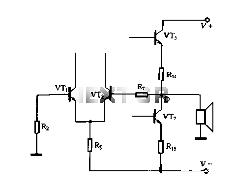
OCL yourself feedback amplifier analysis
The DC feedback circuit is illustrated in Figure 1-31. In this circuit, resistor R7 is connected to the output terminal, which is the midpoint of the static differential input stage voltage Vr, between the base terminals. This configuration represents a...
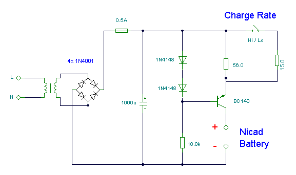
Nicad Battery Charger
This simple charger utilizes a single transistor as a constant current source. The voltage across a pair of 1N4148 diodes biases the base of the BD140 medium power transistor. The base-emitter voltage of the transistor and the forward voltage drop...
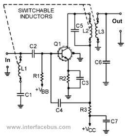
Transistor Circuits
This page presents several transistor circuits that are not commonly found on other pages due to the absence of a specific topic. These circuits, however, illustrate particular points but lack detailed descriptions. An example of an RF amplifier circuit using...
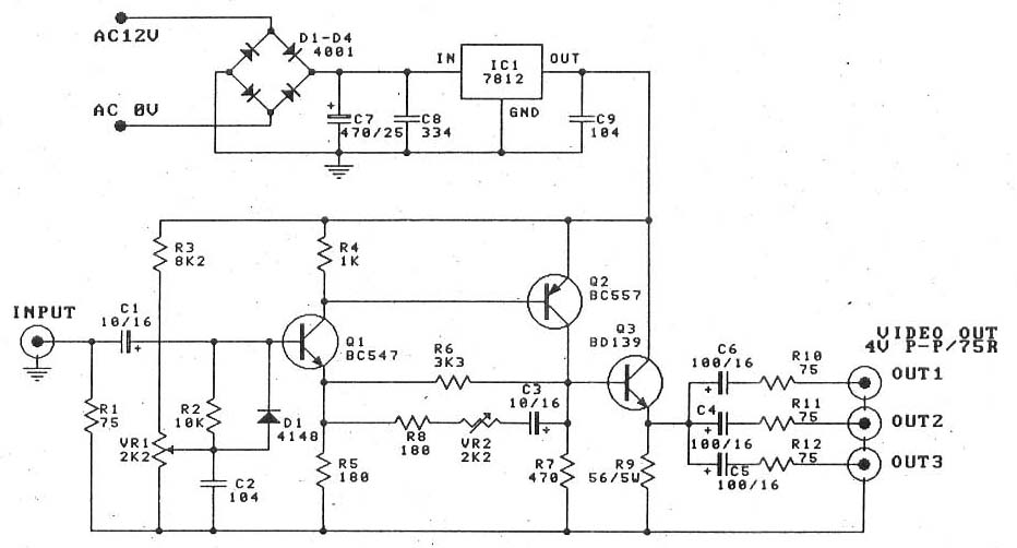
Video amplifier splitter by transistor BD137-BC547-BC557
This is a video amplifier circuit or video splitter circuit, designed to strengthen video signals. It compensates for signal loss and is...
The video amplifier circuit serves as a crucial component in video signal distribution systems, ensuring that the integrity and...
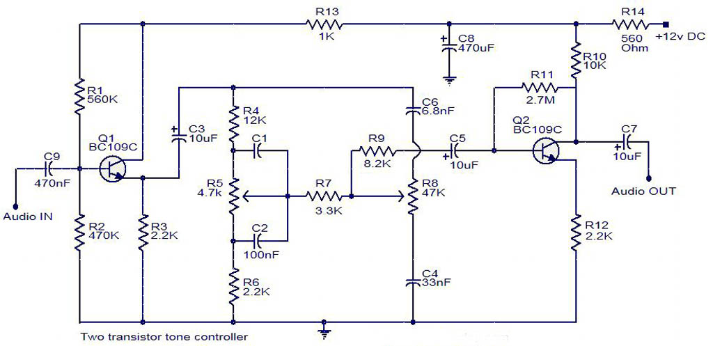
tone controller circuit diagram two transistor
The electrical schematic diagram presented below illustrates a simple two-transistor tone controller audio circuit, which is available for free download. This circuit is based on the well-known Baxandall tone control design. Variations in the values of the transistor components in...
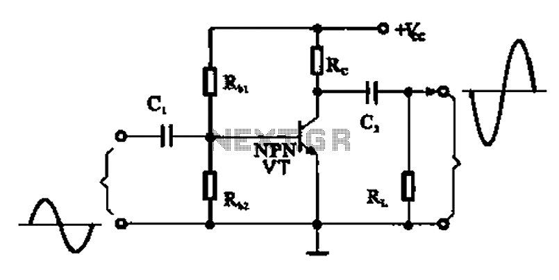
A common emitter amplifier
A common emitter amplifier is a total pole amplification circuit structure featuring a key emitting device. This circuit refers to the emitter of the input signal and the output signal connected to a common ground, forming the basis of fundamental...
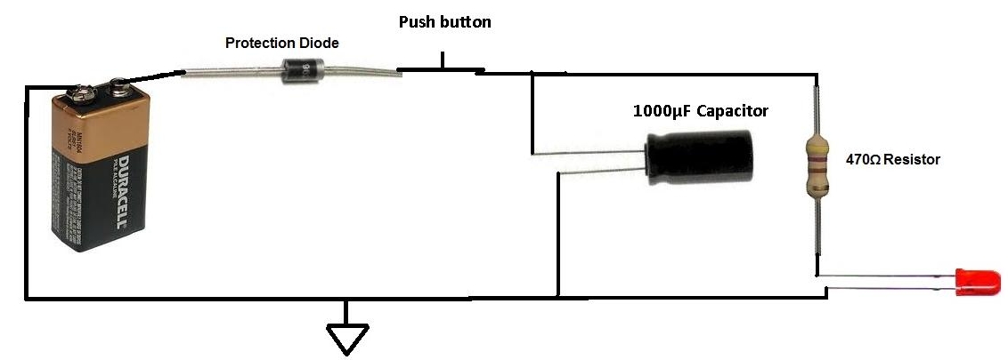
Charged Capacitor to Light an LED
This project involves charging a capacitor with voltage, which will subsequently serve as a temporary power source for the circuit. After charging the capacitor with a battery, the battery is disconnected from the circuit. The capacitor then provides current to...
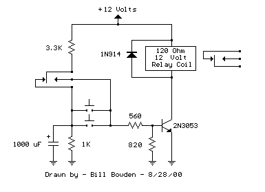
1 Transistor Toggle Relay schematic
The circuit below requires a double pole, double throw relay in conjunction with a single transistor to allow toggling the relay with a momentary push button. One set of relay contacts is used to control the load, while the other...