


DIGITAL_FOURIER
#sine-wave generator
#Walsh-function
#7493
#opamp
#square-wave
#filter
#frequency
#digital expander
#converter
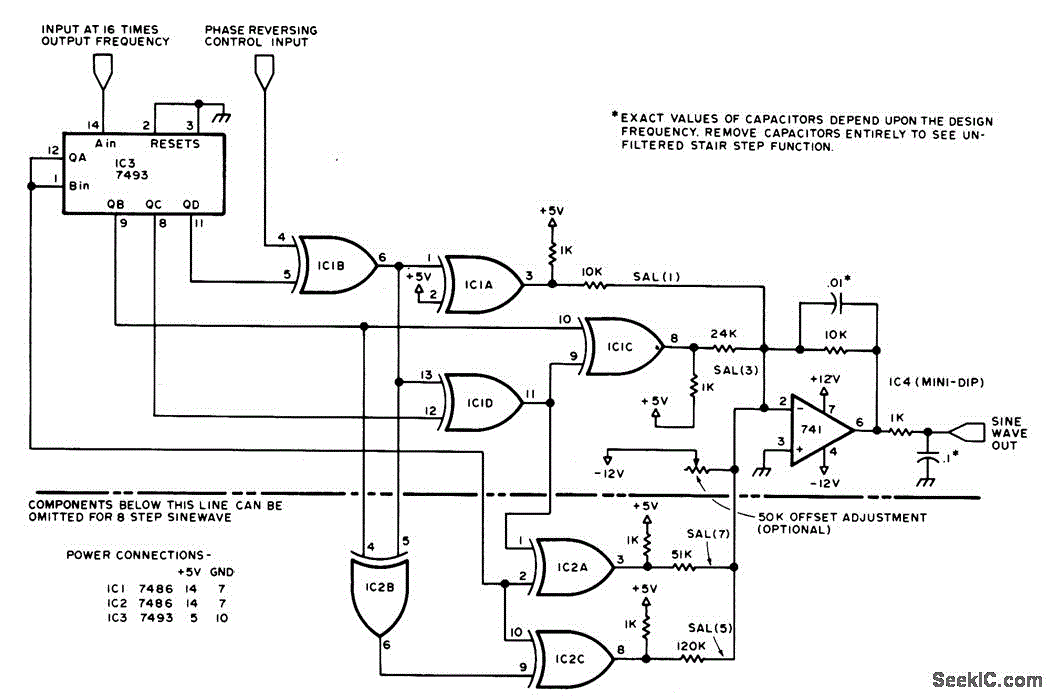
Description: A sine-wave generator produces a Walsh-function approximation of the sine function. The frequency of the sine wave is determined by a square-wave input to pin 14 of a 7493 integrated circuit. Filter components of the operational amplifier assist in smoothing the staircase waveform generated by summing Walsh-function components, which are weighted by resistors. The circuit functions as a converter that includes a digital expander to expand the input square wave.
The sine-wave generator circuit utilizes a 7493 binary counter to generate a square wave input that defines the frequency of the output sine wave. The square wave is fed into pin 14 of the 7493, which is configured to produce a series of binary outputs. These outputs are then processed to create Walsh functions, which are mathematical functions that serve as orthogonal basis functions. The Walsh functions are combined in such a way that they approximate a sine wave.
To achieve the smoothing of the staircase waveform, an operational amplifier (op-amp) is employed. The op-amp is configured in a low-pass filter arrangement, which effectively reduces the high-frequency components of the staircase waveform. The filter components, including resistors and capacitors, are selected to ensure that the desired frequency response is achieved, allowing for a smooth transition between the discrete steps of the staircase waveform.
The weighting of the Walsh-function components is accomplished through a network of resistors that determine the contribution of each component to the final output. This weighting process is crucial for accurately shaping the output waveform to closely resemble a true sine wave.
In addition to the sine-wave generation, the circuit also includes a digital expander. This component expands the input square wave, allowing for a broader range of output frequencies and improving the versatility of the circuit. The digital expander operates by taking the input signal and generating additional output signals that replicate the characteristics of the original square wave, thereby enhancing the overall performance of the sine-wave generator.
Overall, this circuit design provides an effective method for generating sine waves using digital components and analog filtering techniques, making it suitable for various applications in signal processing and waveform generation.Sine-wave generator produces Walsh-function approximation of sine function. Frequency of sine wave is set by square-wave input to pin 14 of 7493. Filter com ponents of opamp help smooth staircase wave form generated by summing Walsh-function components as weighted by resistors. Circuit is converter consisting of digital expander that expands input square wav..
The sine-wave generator circuit utilizes a 7493 binary counter to generate a square wave input that defines the frequency of the output sine wave. The square wave is fed into pin 14 of the 7493, which is configured to produce a series of binary outputs. These outputs are then processed to create Walsh functions, which are mathematical functions that serve as orthogonal basis functions. The Walsh functions are combined in such a way that they approximate a sine wave.
To achieve the smoothing of the staircase waveform, an operational amplifier (op-amp) is employed. The op-amp is configured in a low-pass filter arrangement, which effectively reduces the high-frequency components of the staircase waveform. The filter components, including resistors and capacitors, are selected to ensure that the desired frequency response is achieved, allowing for a smooth transition between the discrete steps of the staircase waveform.
The weighting of the Walsh-function components is accomplished through a network of resistors that determine the contribution of each component to the final output. This weighting process is crucial for accurately shaping the output waveform to closely resemble a true sine wave.
In addition to the sine-wave generation, the circuit also includes a digital expander. This component expands the input square wave, allowing for a broader range of output frequencies and improving the versatility of the circuit. The digital expander operates by taking the input signal and generating additional output signals that replicate the characteristics of the original square wave, thereby enhancing the overall performance of the sine-wave generator.
Overall, this circuit design provides an effective method for generating sine waves using digital components and analog filtering techniques, making it suitable for various applications in signal processing and waveform generation.Sine-wave generator produces Walsh-function approximation of sine function. Frequency of sine wave is set by square-wave input to pin 14 of 7493. Filter com ponents of opamp help smooth staircase wave form generated by summing Walsh-function components as weighted by resistors. Circuit is converter consisting of digital expander that expands input square wav..
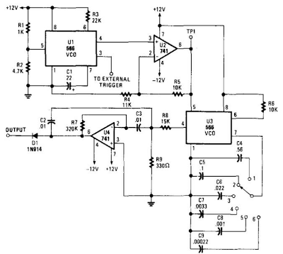
Simple Audio Filter Analyzer Circuit
When this circuit is connected to a filter and an oscilloscope, the oscilloscope displays the filter's frequency response. A frequency that sweeps from low to high is applied to a filter. The oscilloscope is triggered by the start of the...
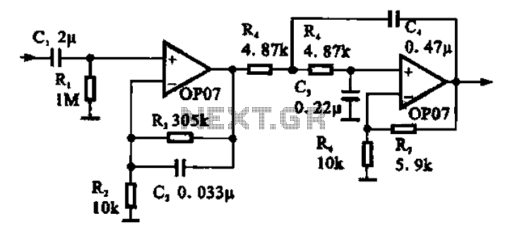
Broadband 0.1 to 10Hz filter amplifier
Broadband 0.1 to 10 Hz filter amplifier. The broadband circuit consists of two operational amplifiers configured as filter amplifiers operating in the frequency range of 0.1 to 10 Hz.
The broadband filter amplifier circuit utilizes two operational amplifiers (op-amps) to achieve...
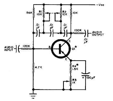
Q-multiplier filter circuit
This circuit is designed for selective tuning adjustments between two closely spaced audio tones. The frequency is determined by the values of the capacitors and resistors in the feedback circuit connecting the collector and base of transistor Q1. With the...
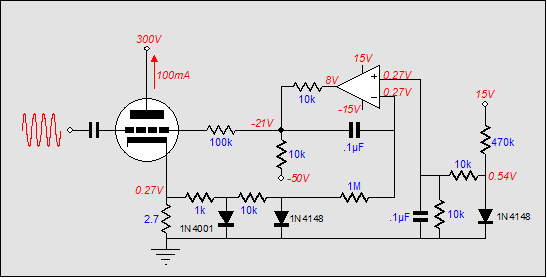
Broskie auto-bias circuit
It is embarrassing to acknowledge that the blog post from April 29 contained several schematic errors of my own making, particularly in the variation of Morgan Jones's circuit. One of the resistor values was incorrect by a factor of ten,...
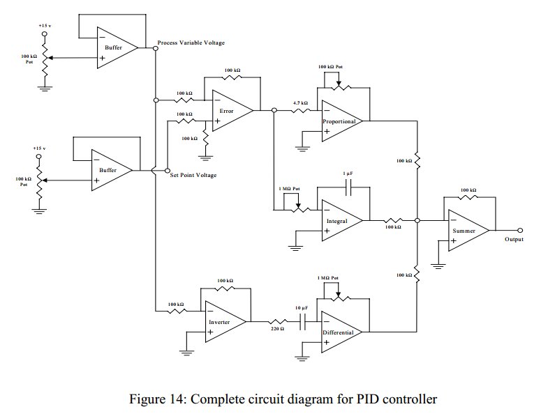
converting circuits to c
Convert a feedforward operational amplifier PID loop to C code. Assistance is needed for this conversion, as the process is unfamiliar. Input values can be obtained through an ADC, such as voltage or current, but coding a feedforward PID is...
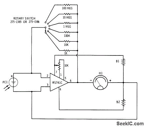
SIX RANGE LIGHT METER
The circuit involves the switching of feedback resistors for an operational amplifier (op-amp) that is driven by a Radio Shack 276-115 selenium solar cell, resulting in a multirange linear light meter. A 1000-megohm resistor is utilized for the highest sensitivity,...
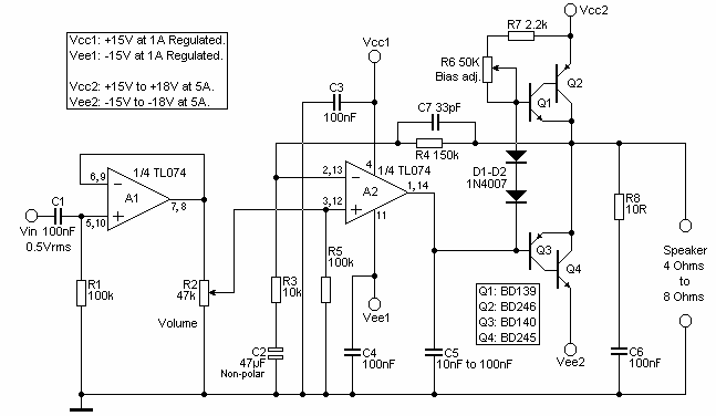
Opamp Based Power Amplifier
The amplifier is based on the commonly used class-AB complementary power amplifier with compound pair output transistors. The system uses a TL074 quad opamp to drive the output transistors. As can be seen from figure 1, A2 is used to...
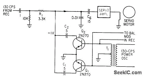
SYNCHRONOUS FILTER FOR ADF
Separates 130-cps motor drive voltage from voice frequencies in the output of an ADF receiver. P. V. Sparks, Servo Filter and Gain Control Improve Automatic Direction Finder, Electronics, 34:23, p 110-113.
The circuit described functions as a filter that effectively separates...
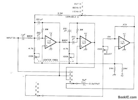
Filter Circuit
The circuit utilizing Optical Electronics 9803 operational amplifiers separates an audio frequency (AF) input signal into two outputs. The low-pass output allows frequencies from DC up to 10 Hz, while the high-pass output encompasses frequency content above 10 Hz, reaching...