


Digital oscillator
#digital oscillator
#CMOS
#buffer inverters
#variable resistance
#low cost
#frequency
#capacitors
#4V-18V
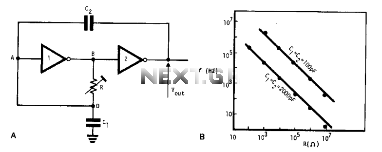
Description: This simple, low-cost oscillator is constructed using two CMOS buffer inverters, two capacitors, and a variable resistor. The circuit operates with voltage levels ranging from 4 V to 18 V. When C1 equals C2, the frequency of oscillation is determined.
The described oscillator circuit utilizes two CMOS buffer inverters which serve as the primary active components for generating oscillations. The configuration of these inverters allows for feedback that sustains oscillation. The two capacitors (C1 and C2) are crucial for determining the timing characteristics of the oscillator. When both capacitors are equal in value, the frequency of oscillation can be calculated using the formula:
\[ f = \frac{1}{2 \pi R C} \]
where \( R \) is the resistance set by the variable resistor and \( C \) is the capacitance value of either capacitor (since C1 = C2).
The variable resistor allows for fine-tuning of the oscillation frequency, providing flexibility in applications where different frequencies may be required. The operating voltage range of 4 V to 18 V indicates that this oscillator can be used in various low-power applications, making it suitable for battery-operated devices or low-voltage circuits.
In terms of input and output impedance, the circuit's performance may be influenced by these parameters. However, they are typically considered negligible for the basic operation of this oscillator. When implementing this circuit, it is essential to ensure that the power supply is stable and within the specified voltage range to maintain consistent oscillation performance.
Overall, this CMOS-based oscillator circuit is an efficient solution for generating square wave signals in various electronic applications, including timers, clock generators, and signal modulation systems. Its simplicity and low cost make it an attractive option for hobbyists and professionals alike.This very simple, low cost oscillator, is built with two CMOS buffer inverters, two capacitors and a variable resistance. The circuit can work with voltages ranging from 4 V up to 18 V. If Cl = C2, the frequency of oscillation. Ignoring the output and input impedance is given.
The described oscillator circuit utilizes two CMOS buffer inverters which serve as the primary active components for generating oscillations. The configuration of these inverters allows for feedback that sustains oscillation. The two capacitors (C1 and C2) are crucial for determining the timing characteristics of the oscillator. When both capacitors are equal in value, the frequency of oscillation can be calculated using the formula:
\[ f = \frac{1}{2 \pi R C} \]
where \( R \) is the resistance set by the variable resistor and \( C \) is the capacitance value of either capacitor (since C1 = C2).
The variable resistor allows for fine-tuning of the oscillation frequency, providing flexibility in applications where different frequencies may be required. The operating voltage range of 4 V to 18 V indicates that this oscillator can be used in various low-power applications, making it suitable for battery-operated devices or low-voltage circuits.
In terms of input and output impedance, the circuit's performance may be influenced by these parameters. However, they are typically considered negligible for the basic operation of this oscillator. When implementing this circuit, it is essential to ensure that the power supply is stable and within the specified voltage range to maintain consistent oscillation performance.
Overall, this CMOS-based oscillator circuit is an efficient solution for generating square wave signals in various electronic applications, including timers, clock generators, and signal modulation systems. Its simplicity and low cost make it an attractive option for hobbyists and professionals alike.This very simple, low cost oscillator, is built with two CMOS buffer inverters, two capacitors and a variable resistance. The circuit can work with voltages ranging from 4 V up to 18 V. If Cl = C2, the frequency of oscillation. Ignoring the output and input impedance is given.
Driver circuits
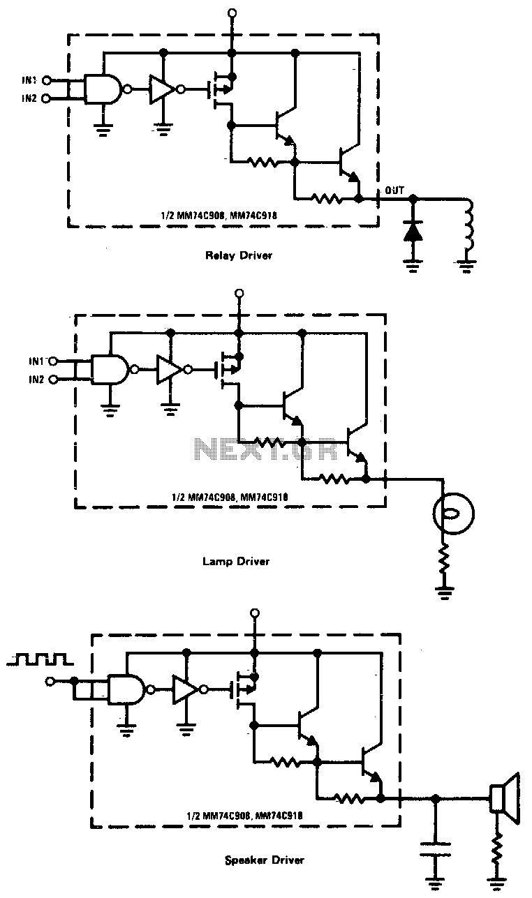
CMOS drivers for relays, lamps, speakers, and similar applications provide extremely low standby power consumption. When operating at Vcc = 15 V, the power dissipation per package is typically 750 nW when the outputs are not drawing current. Consequently, these...
CD4013 Push Button CMOS Toggle Flip Flop
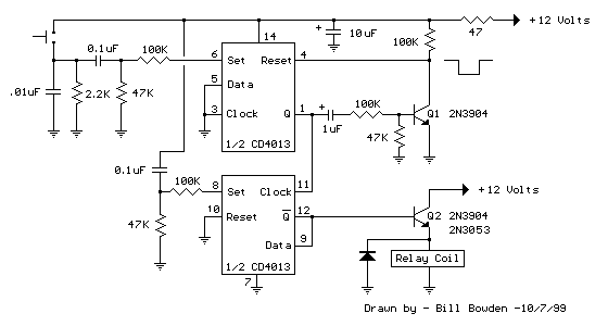
The circuit utilizes a CMOS dual D flip-flop (CD4013) to toggle a relay or other load using a momentary push button. Multiple push buttons can be connected in parallel to control the relay from various locations. A high signal from...
Toggle Switch No.1 - Cmos 4013
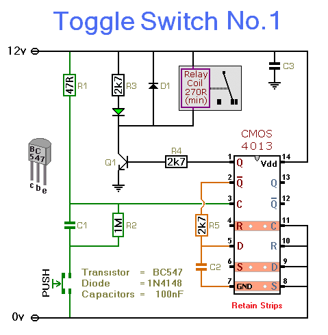
This circuit energizes and de-energizes a relay with the push of a button. Any momentary push-to-make switch can be utilized. Pressing the button once energizes the relay, while pressing it a second time de-energizes the relay. The circuit is illustrated...
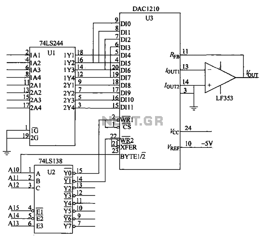
CMOS interface circuit with the PMOS cross-c
CMOS interface circuit with PMOS cross-coupled PMOS integrated circuit featuring high input impedance, where the input current can be ignored. The CMOS and PMOS interface circuit is illustrated in the accompanying figure.
The CMOS interface circuit utilizing PMOS cross-coupled configurations is...
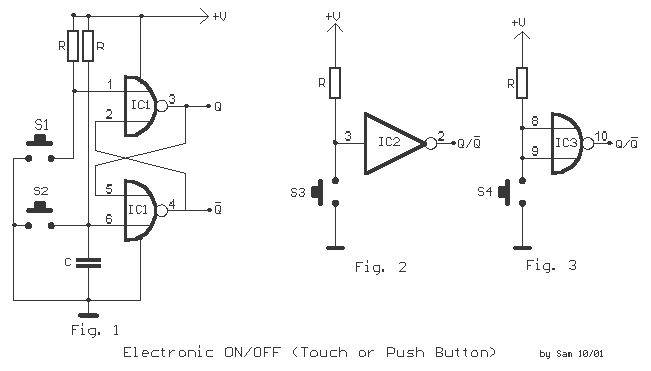
Electronic Switch ON-OFF
Here we have three choices, with which we can make electronic switches that use our touch or pressing (push button). We thus exploit the very big resistance of entry, that present the gates CMOS. In the fig.1 we have two...
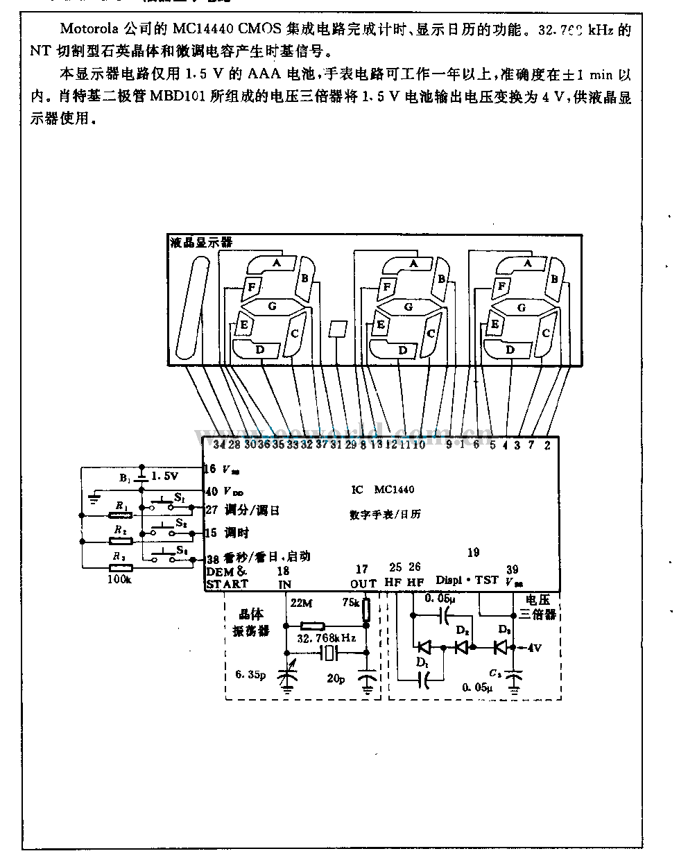
1.5V liquid crystal display circuit
The Motorola company's MC14440 CMOS integrated circuit is designed for timing and displaying calendar functions. It utilizes a 32.768 kHz NT cutting type quartz crystal along with fine-tune capacitance to generate time-based signals. The display circuit operates on a 1.5...
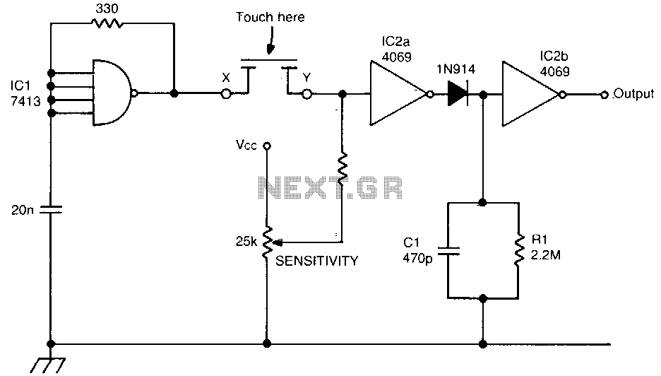
Cmos touch switch
This touch switch does not rely on mains hum for switching; it can be used with battery-powered circuits. The Schmitt trigger IC1 forms a 100 kHz oscillator, and IC2a, which is biased into the linear region, amplifies the output and...
Frequency warning alarm
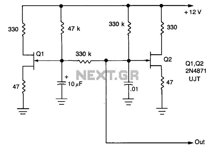
A low-frequency oscillator (Q1) modulates a high-frequency oscillator (Q2) along with its associated timing capacitor. The output frequency varies continuously.
The circuit comprises two primary components: the low-frequency oscillator (Q1) and the high-frequency oscillator (Q2). The low-frequency oscillator is responsible for...
Cmos-universal-logic-probe
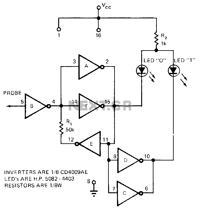
The circuit requires only the CD4009AE hex buffer, two resistors, and two LEDs to create a logic probe. This CMOS logic probe has an input impedance of 10^12 ohms and operates within a voltage range of 3 to 15 volts....