


Electronic Gain Control in Quartz-Stabilized Oscillator
#quartz
#stabilized oscillator
#electronic gain control
#amplitude stabilization
#crystal oscillator
#frequency control
#circuit design
#electronics
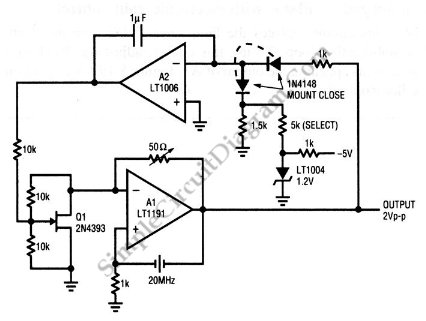
Description: This is a quartz-stabilized oscillator circuit with electronic gain control. Replacing the common filament lamp for amplitude stabilization, this circuit uses...
This circuit represents a quartz-stabilized oscillator featuring electronic gain control, which enhances the stability and precision of the output frequency. The utilization of a quartz crystal allows for high-frequency accuracy, making this oscillator suitable for various applications requiring stable signal generation.
In this design, the traditional filament lamp, often employed for amplitude stabilization, has been replaced with a more efficient electronic gain control mechanism. This substitution not only improves the reliability of the circuit but also reduces power consumption and increases the overall lifespan of the oscillator.
The circuit typically includes a quartz crystal oscillator, which sets the fundamental frequency, and an amplifier stage that provides the necessary gain. The electronic gain control is implemented using a variable resistor or a digital potentiometer, allowing for real-time adjustments to the amplitude of the output signal. Feedback loops are utilized to maintain the desired output level and to ensure that the oscillator remains stable under varying load conditions.
Power supply considerations are also crucial for the performance of this circuit. A regulated power supply is recommended to minimize noise and fluctuations that could affect the oscillator's stability. Additionally, decoupling capacitors should be placed close to the power pins of the active components to filter out high-frequency noise.
In summary, this quartz-stabilized oscillator circuit with electronic gain control offers a modern solution for generating stable frequencies with enhanced performance characteristics compared to traditional methods. Its design allows for flexibility in applications, making it suitable for communication systems, signal processing, and other electronic devices requiring precise frequency generation.This is a quartz-stabilized oscillator circuit with electronic gain control. Replacing the common filament lamp for amplitude stabilization, this circuit use..
This circuit represents a quartz-stabilized oscillator featuring electronic gain control, which enhances the stability and precision of the output frequency. The utilization of a quartz crystal allows for high-frequency accuracy, making this oscillator suitable for various applications requiring stable signal generation.
In this design, the traditional filament lamp, often employed for amplitude stabilization, has been replaced with a more efficient electronic gain control mechanism. This substitution not only improves the reliability of the circuit but also reduces power consumption and increases the overall lifespan of the oscillator.
The circuit typically includes a quartz crystal oscillator, which sets the fundamental frequency, and an amplifier stage that provides the necessary gain. The electronic gain control is implemented using a variable resistor or a digital potentiometer, allowing for real-time adjustments to the amplitude of the output signal. Feedback loops are utilized to maintain the desired output level and to ensure that the oscillator remains stable under varying load conditions.
Power supply considerations are also crucial for the performance of this circuit. A regulated power supply is recommended to minimize noise and fluctuations that could affect the oscillator's stability. Additionally, decoupling capacitors should be placed close to the power pins of the active components to filter out high-frequency noise.
In summary, this quartz-stabilized oscillator circuit with electronic gain control offers a modern solution for generating stable frequencies with enhanced performance characteristics compared to traditional methods. Its design allows for flexibility in applications, making it suitable for communication systems, signal processing, and other electronic devices requiring precise frequency generation.This is a quartz-stabilized oscillator circuit with electronic gain control. Replacing the common filament lamp for amplitude stabilization, this circuit use..
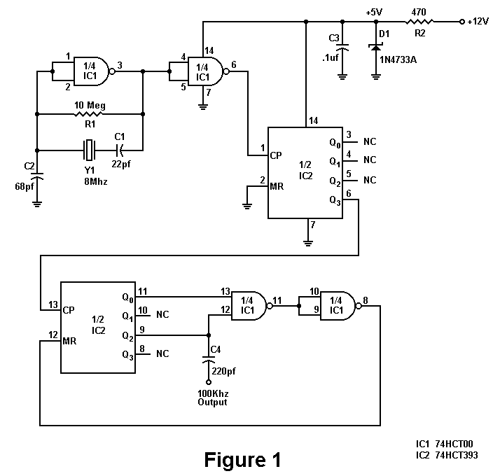
100KHz Crystal Oscillator
There is a significant amount of vintage amateur equipment that many enthusiasts have chosen to restore and rejuvenate. Although many early amateur transceivers operate effectively, they typically lack a digital readout and depend on analog dials for tuning. The challenge...
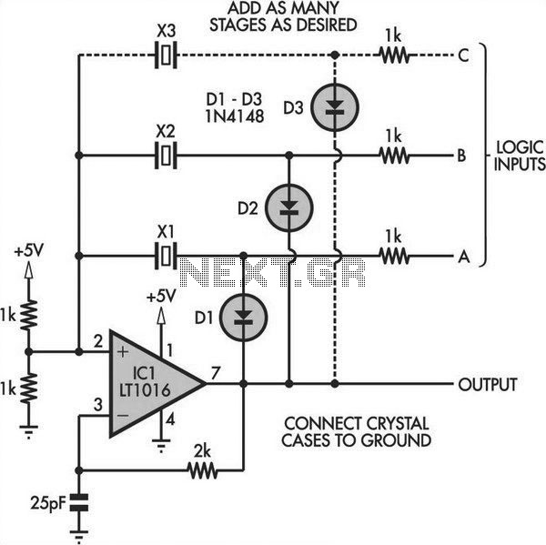
Switchable Output Crystal Oscillator
Switchable Output Crystal Oscillator Circuit. This oscillator circuit allows crystals to be electronically switched using logic commands. The circuit is best understood by initially ignoring all crystals. Furthermore, assume that a...
The switchable output crystal oscillator circuit is designed to provide...
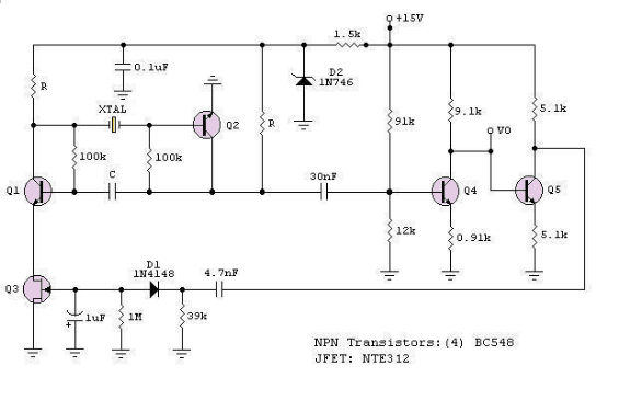
A Low-Frequency Crystal Controlled Oscillator
The RF engineer often needs an instrument that can reliably and quickly test a low-frequency quartz crystal unit. However, such equipment is challenging to find, and engineers frequently consult electronic circuit handbooks for schematics that can accomplish this task. Unfortunately,...
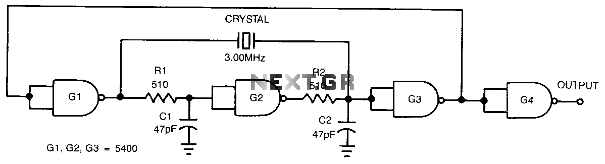
Easy-start-up-crystal-oscillator
This low-cost, crystal-controlled oscillator employs a single TTL gate. Two key factors facilitate the oscillator's start-up: the configuration of NAND gates G1, G2, and G3 in an unstable logic state, and the high loop gain provided by the three inverters....
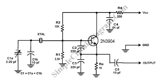
Colpitts Crystal Oscillator
A Crystal Colpitts oscillator can be constructed using a parallel mode crystal and a transistor. The circuit is depicted in the accompanying figure. In this configuration, an inductance is utilized.
The Crystal Colpitts oscillator is a type of electronic oscillator that...
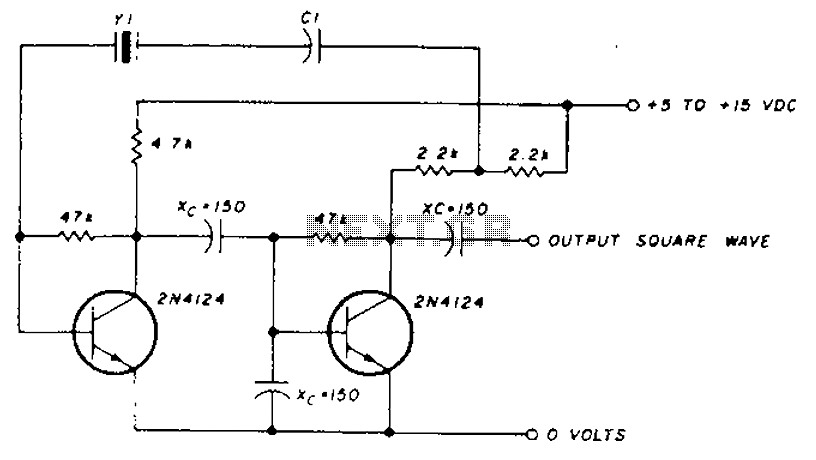
Frequency crystal oscillator circuit diagram of 10kHz-150kHz
A transistor in series with capacitor C1 can be utilized to adjust the oscillator output frequency. The frequency may vary with changes in capacitance ranging from 20 pF to 0.01 µF, or as determined by the tuning capacitor. The transistor...
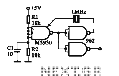
Crystal oscillator DTL integrated circuit
A crystal oscillator is implemented using a DTL (Diode-Transistor Logic) integrated circuit. The oscillation frequencies are 100 kHz and 1 MHz. The circuit consists of a gate circuit that generates a signal for the oscillator circuitry in DTL.
The crystal oscillator...
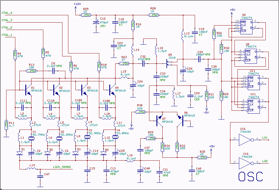
The local oscillator for 10.7 to 2.5MHz conversion
A 52 MHz third overtone crystal typically has a series resonance impedance of 30 ohms as per manufacturer specifications. The crystals utilized in the prototypes exhibit nearly ten times lower series resistance but are significantly more expensive. An oscillator can...
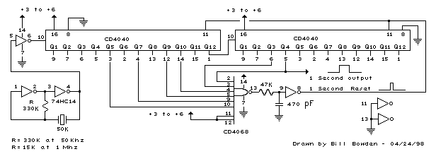
Crystal Oscillator counter
Using a 50 Khz crystal, a count of 50000 is detected when the appropriate counter bits that add up to 50000 are all high. This corresponds to bits 15 (32768) + 14 (16384) + 9 (512) + 8 (256) +...