


Field scanning circuit circuit and sawtooth waveforms
#sawtooth waveform
#signal generation
#field scanning
#television
#Toshiba
#waveform generator
#analog circuit
#video signal
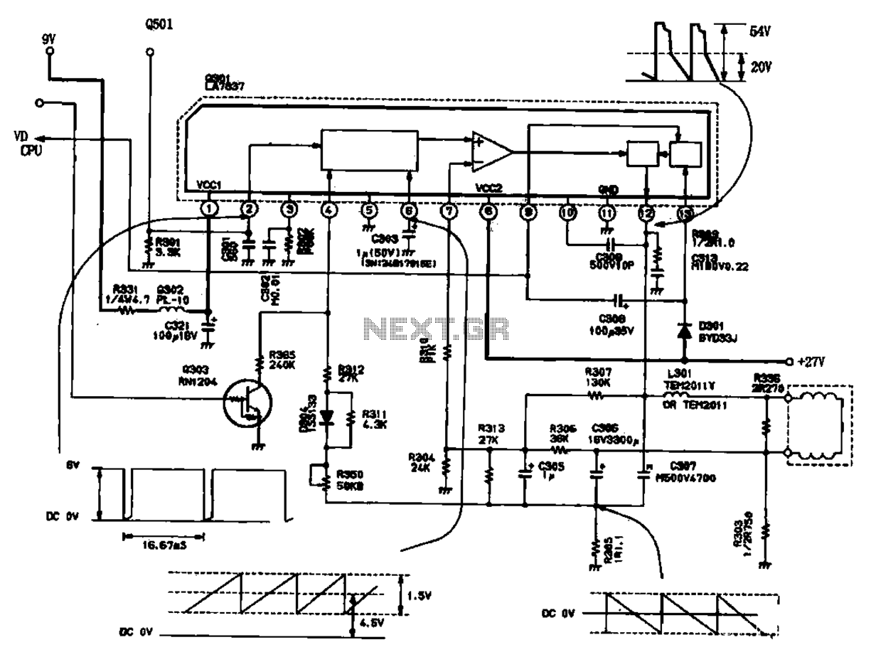
Description: The field scanning circuit generates sawtooth waveforms essential for color television field scanning. The circuit, as illustrated in Figure 1, is utilized in the Toshiba 2150 TV. The vertical scan pulse signal is produced from the LA7837 integrated circuit, which first processes the input into a sawtooth waveform. This sawtooth signal can be measured at the output pins. It is then amplified through an amplifier and subsequently passed through a power amplifier output stage. The peak scanning signal output reaches approximately 54V, which is directed to the deflection coil, powered by a main supply of -2V.
The field scanning circuit is a critical component in color television systems, responsible for generating the vertical synchronization signals that drive the display. The LA7837 integrated circuit serves as the heart of this operation, converting a stable input signal into a sawtooth waveform essential for vertical deflection. The sawtooth waveform is characterized by its linear rise and rapid fall, which is ideal for creating the necessary timing for scanning the display from top to bottom.
In the circuit, the sawtooth waveform is first generated within the LA7837, where it is shaped to provide the correct timing characteristics. The output from this stage is typically measured at specific pins of the IC, allowing for monitoring and adjustment of the waveform as needed. Following this, the sawtooth signal is amplified to ensure it has sufficient power to drive the deflection coils effectively. This amplification stage is crucial, as the output needs to be strong enough to overcome any load presented by the deflection system.
The final output stage involves a power amplifier that boosts the signal to a peak voltage of approximately 54V. This high voltage is necessary to drive the deflection coils, which are responsible for moving the electron beam across the screen in a controlled manner. The deflection coils require a significant amount of current to produce the magnetic fields necessary for the beam's movement, hence the need for such a high output voltage.
The main power supply for this circuit operates at -2V, which is a standard requirement for many television circuits to ensure proper biasing and operation of the components involved. Overall, the field scanning circuit exemplifies the integration of analog signal processing with power amplification to achieve the desired performance in television display technology.Field scanning circuit circuit and sawtooth waveforms Sawtooth signal generating circuit color television field scan is an indispensable circuit shown in Figure 1 is a Toshiba 2150 TV field output waveform signal level and the structure of the circuit, the field vertical scan pulse signal generating circuit is supplied from the LA7837 feet in the IC first into the saw tooth wave signal forming circuit, can be measured in feet sawtooth signal. And then amplified by the amplifier, and finally the power amplifier output stage after the pin output peak scanning signal of about 54V.
Sent to the deflection coil, the main power supply {-2V ( feet)
The field scanning circuit is a critical component in color television systems, responsible for generating the vertical synchronization signals that drive the display. The LA7837 integrated circuit serves as the heart of this operation, converting a stable input signal into a sawtooth waveform essential for vertical deflection. The sawtooth waveform is characterized by its linear rise and rapid fall, which is ideal for creating the necessary timing for scanning the display from top to bottom.
In the circuit, the sawtooth waveform is first generated within the LA7837, where it is shaped to provide the correct timing characteristics. The output from this stage is typically measured at specific pins of the IC, allowing for monitoring and adjustment of the waveform as needed. Following this, the sawtooth signal is amplified to ensure it has sufficient power to drive the deflection coils effectively. This amplification stage is crucial, as the output needs to be strong enough to overcome any load presented by the deflection system.
The final output stage involves a power amplifier that boosts the signal to a peak voltage of approximately 54V. This high voltage is necessary to drive the deflection coils, which are responsible for moving the electron beam across the screen in a controlled manner. The deflection coils require a significant amount of current to produce the magnetic fields necessary for the beam's movement, hence the need for such a high output voltage.
The main power supply for this circuit operates at -2V, which is a standard requirement for many television circuits to ensure proper biasing and operation of the components involved. Overall, the field scanning circuit exemplifies the integration of analog signal processing with power amplification to achieve the desired performance in television display technology.Field scanning circuit circuit and sawtooth waveforms Sawtooth signal generating circuit color television field scan is an indispensable circuit shown in Figure 1 is a Toshiba 2150 TV field output waveform signal level and the structure of the circuit, the field vertical scan pulse signal generating circuit is supplied from the LA7837 feet in the IC first into the saw tooth wave signal forming circuit, can be measured in feet sawtooth signal. And then amplified by the amplifier, and finally the power amplifier output stage after the pin output peak scanning signal of about 54V.
Sent to the deflection coil, the main power supply {-2V ( feet)
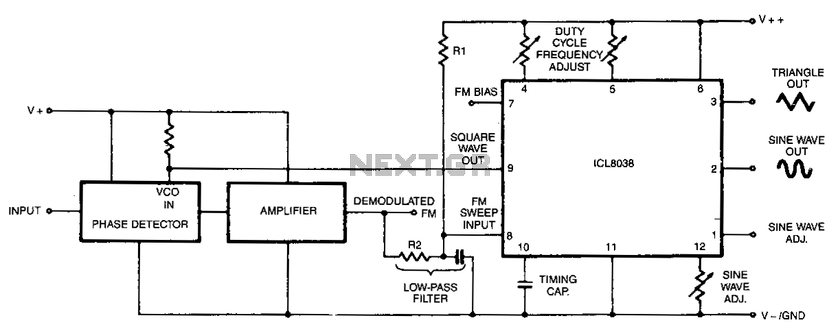
Waveform-generator-stable-vco
In this circuit, a waveform generator is used as a stable voltage-controlled oscillator (VCO) in a Phase-Locked Loop (PLL).
The circuit utilizes a waveform generator configured as a voltage-controlled oscillator (VCO), which is a critical component in the design of a...
TV Muter Circuit
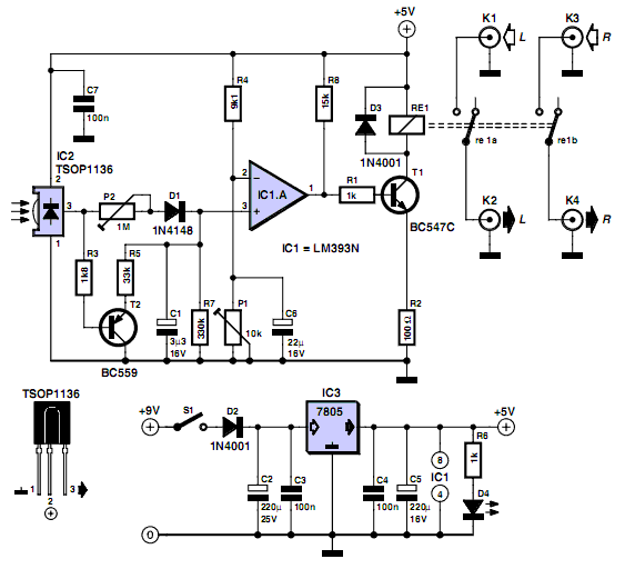
Many households still use tube-type television sets. Connecting these large televisions to a stereo system to enhance sound quality is usually straightforward, as numerous SCART to Cinch adapters are available in accessory shops. However, some television sets may present issues...
TV Muter Circuit
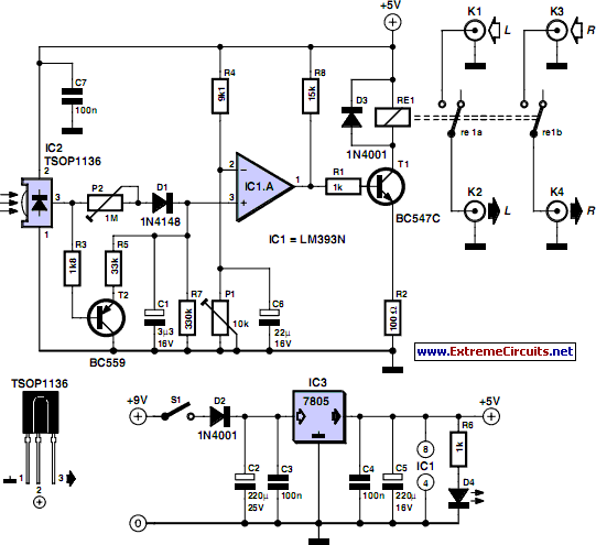
Many households still use tube-type television sets. Connecting one of these large televisions to a stereo system to enhance sound quality is generally straightforward, as numerous SCART to Cinch adapters are available in accessory shops. However, with some television sets,...
Picture-fixer-inverter
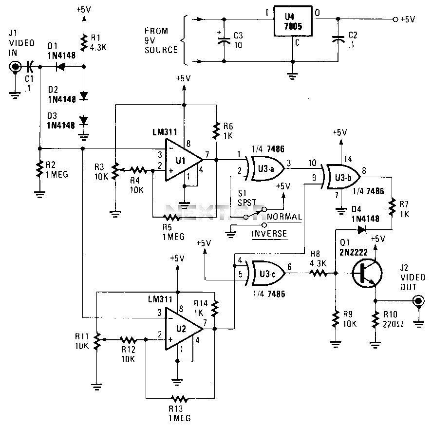
The circuit accepts a video signal, separates the sync pulses, inverts the video, and integrates new video with the existing sync pulses. The video signal is input through J1 and processed by a clamping circuit comprising C1, D1, D2, D3,...
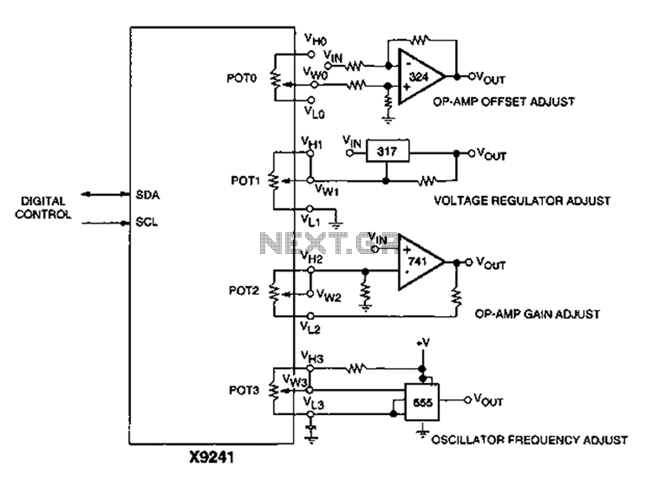
Corrector circuit diagram of an analog circuit
A XICOR X9241 POT IC module can be utilized to modify the four digital analog circuits, as depicted in the schematic.
The XICOR X9241 is a digital potentiometer integrated circuit designed for precise adjustment of analog signal levels in various electronic...
Waveform Generators Circuits
Many applications require low-frequency signal generators that can deliver high-performance, high-resolution signals. This design idea presents a circuit that generates frequencies from 0 to 1 MHz, providing sinusoidal, triangular, and square-wave outputs with frequency resolution better than 0. A DDS...
Video Fader Circuit
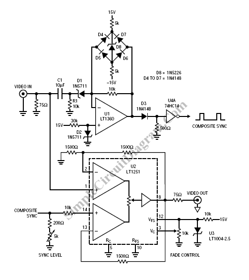
Fading a video signal cannot be achieved merely by attenuating the composite signal, as this may cause the synchronization signal to fall below an unacceptable level.
To effectively fade a video signal while maintaining the integrity of the synchronization components,...
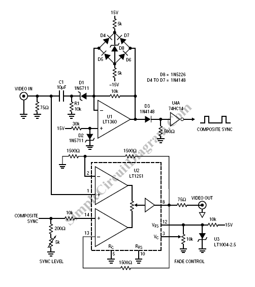
Video Fader Circuit
Fading a video signal cannot be achieved merely by attenuating the composite signal, as the synchronization signal may fall below an unacceptable level.
Fading a video signal involves a careful adjustment of both the luminance and chrominance components while maintaining...
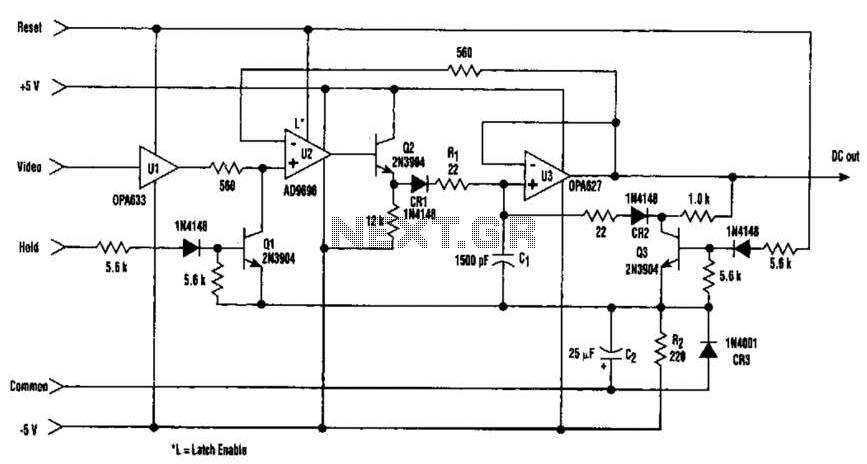
Fast Video Signal Amplitude Measurer Circuit
The amplitude of a video signal can be measured using a straightforward circuit that functions as a modified standard peak detector. This device is capable of verifying RGB signals produced by video RAMDACs. U1 is a high-speed buffer, while U2...