


fm oscillator with bly87
#fm oscillator
#BLY87
#ceramic capacitors
#trimmer capacitor
#inductor
#RF
#frequency modulation
#tuning
#resonance
#electronic components
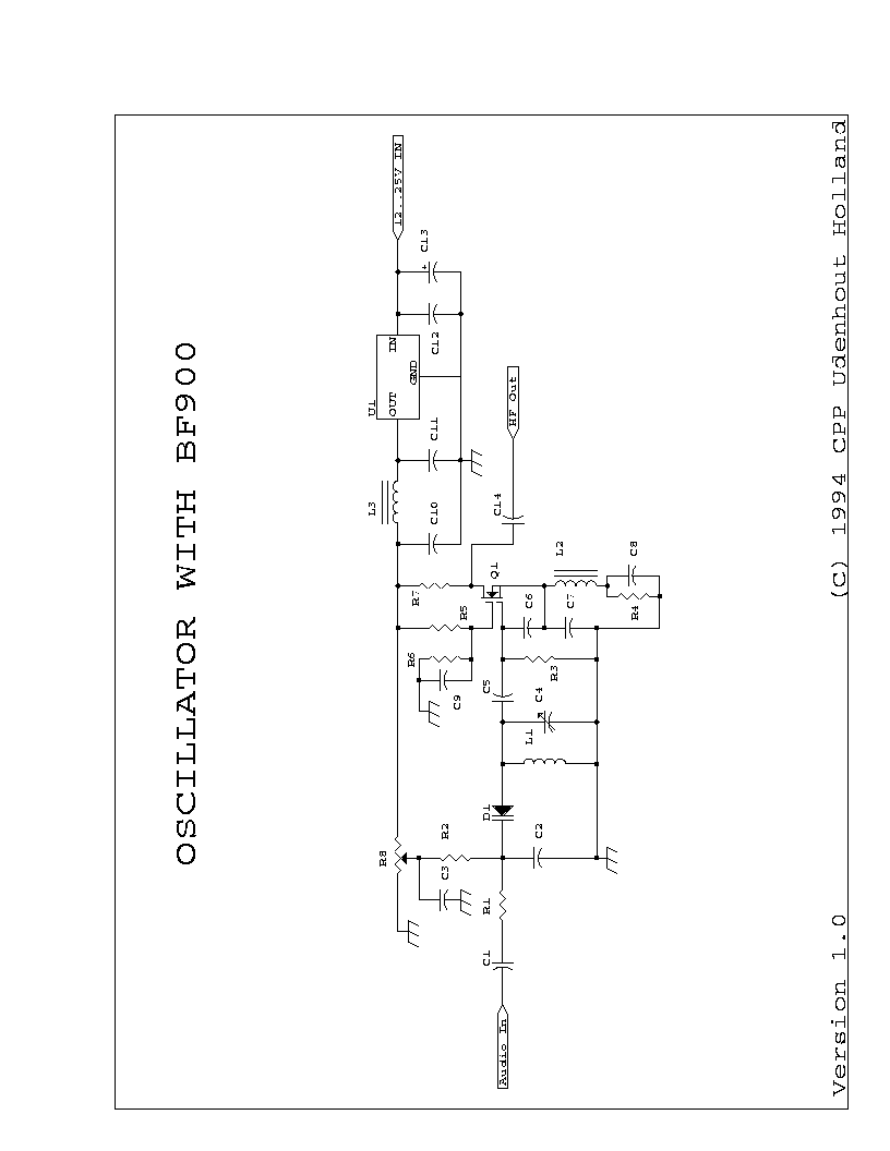
Description: C1 = 100 nF multilayer or ceramic capacitor; C2 = 4.7 pF ceramic capacitor; C3 = 100 nF ceramic capacitor (1 nF or 10 nF can also be used); C4 = 40 pF trimmer capacitor; C5 = 4.7 pF ceramic capacitor; C6 = 10 pF ceramic capacitor; C7 = 22 pF ceramic capacitor; C8 = 1 nF ceramic capacitor; C9 = 1 nF ceramic capacitor; C10 = 100 nF ceramic capacitor; C11 = 100 nF ceramic capacitor; C12 = 100 nF ceramic capacitor; C13 = 47 µF/25V electrolytic capacitor; C14 = 1 nF ceramic capacitor. L1 is a coil with 4 turns, a diameter of 8 mm, using 1 mm CuAg wire with a spacing of 1 mm, mounted 8 mm above the PCB (leads are 4 mm). L2 and L3 are 6-hole Ferroxcube wideband HF chokes with 5 turns each. This package includes the schematic and PCB layout for an FM oscillator utilizing the BF900 dual gate MOSFET, designed to operate between 90 MHz and 110 MHz, characterized by low noise and high stability. Proper buffering eliminates the need for a phase-locked loop (PLL). Mounting holes for the BF900 should be created with a diameter of 6 mm to accommodate its casing. A previous issue with the copper on the opposite side of the PCB was resolved by removing a section of copper around the BF900, approximately 1 to 1.5 cm in diameter.
The circuit design primarily features various capacitors and inductors that are essential for the operation of the FM oscillator. The selection of capacitors, including both ceramic and electrolytic types, ensures stability and performance across the desired frequency range. The use of a trimmer capacitor (C4) allows for fine-tuning of the oscillator frequency, which is critical in applications requiring precision.
Inductors L1, L2, and L3 are integral to the circuit, with L1 serving as a tuned circuit element that works in conjunction with the capacitors to establish the oscillator's frequency. The specified dimensions and materials for L1, particularly the use of copper-silver wire, suggest a focus on minimizing resistive losses and enhancing the quality factor (Q) of the inductor. The mounting height of L1 above the PCB is also significant, as it influences the magnetic coupling and overall inductance.
The BF900 dual gate MOSFET is chosen for its low noise characteristics, making it suitable for RF applications. Its design allows for high-frequency operation, which is essential for FM transmission. The recommendation for proper buffering indicates a consideration for signal integrity and the prevention of oscillation instability, which can occur in high-frequency circuits.
Overall, the schematic and layout provided in this package are tailored for efficiency and reliability in FM oscillator design, making it suitable for various applications in communication systems where low noise and stability are paramount.C1=100nF Multilayer or ceramic C2 : 4. 7 pF ceramic C3 : 100 nF ceramic (1 or 10 nF will do also) C4 : 40 pf trimmer C5 : 4. 7 pF ceramic C6 : 10 pF ceramic C7 : 22 pF ceramic C8 : 1 nF ceramic C9 : 1 nF ceramic C10: 100 nF ceramic C11: 100 nF ceramic C12: 100 nF ceramic C13: 47 uF/25V C14: 1 nF ceramic L1 : 4 wdg, dia 8 mm, 1 mm CuAg, space 1 mm ; Mounted 8 mm above PCB (Leads are 4 mm) L2 : 6-hole ferroxcube wideband HF-choke (5 wdg) L3 : 6-hole ferroxcube wideband HF-choke (5 wdg) This package contains the schematic and PCB layout for the FM oscillator using the BF900 Dual Gate MOSFET, which is used between 90 and 110 MHz. and that he has a very low noise, and very stable. If you use the proper buffering, a PLL is not needed anymore. For BF900 mounting holes (diameter 6 mm) should be created in which the casing can survive in. I myself have a problem with the other side of the copper`, since the oscillator will not light (not really enough votes Just kidding).
Was solved when I removed the copper BF900 (about 1 1. 5 cm diameter).
The circuit design primarily features various capacitors and inductors that are essential for the operation of the FM oscillator. The selection of capacitors, including both ceramic and electrolytic types, ensures stability and performance across the desired frequency range. The use of a trimmer capacitor (C4) allows for fine-tuning of the oscillator frequency, which is critical in applications requiring precision.
Inductors L1, L2, and L3 are integral to the circuit, with L1 serving as a tuned circuit element that works in conjunction with the capacitors to establish the oscillator's frequency. The specified dimensions and materials for L1, particularly the use of copper-silver wire, suggest a focus on minimizing resistive losses and enhancing the quality factor (Q) of the inductor. The mounting height of L1 above the PCB is also significant, as it influences the magnetic coupling and overall inductance.
The BF900 dual gate MOSFET is chosen for its low noise characteristics, making it suitable for RF applications. Its design allows for high-frequency operation, which is essential for FM transmission. The recommendation for proper buffering indicates a consideration for signal integrity and the prevention of oscillation instability, which can occur in high-frequency circuits.
Overall, the schematic and layout provided in this package are tailored for efficiency and reliability in FM oscillator design, making it suitable for various applications in communication systems where low noise and stability are paramount.C1=100nF Multilayer or ceramic C2 : 4. 7 pF ceramic C3 : 100 nF ceramic (1 or 10 nF will do also) C4 : 40 pf trimmer C5 : 4. 7 pF ceramic C6 : 10 pF ceramic C7 : 22 pF ceramic C8 : 1 nF ceramic C9 : 1 nF ceramic C10: 100 nF ceramic C11: 100 nF ceramic C12: 100 nF ceramic C13: 47 uF/25V C14: 1 nF ceramic L1 : 4 wdg, dia 8 mm, 1 mm CuAg, space 1 mm ; Mounted 8 mm above PCB (Leads are 4 mm) L2 : 6-hole ferroxcube wideband HF-choke (5 wdg) L3 : 6-hole ferroxcube wideband HF-choke (5 wdg) This package contains the schematic and PCB layout for the FM oscillator using the BF900 Dual Gate MOSFET, which is used between 90 and 110 MHz. and that he has a very low noise, and very stable. If you use the proper buffering, a PLL is not needed anymore. For BF900 mounting holes (diameter 6 mm) should be created in which the casing can survive in. I myself have a problem with the other side of the copper`, since the oscillator will not light (not really enough votes Just kidding).
Was solved when I removed the copper BF900 (about 1 1. 5 cm diameter).
RF-Radio Frequency 6
This circuit is designed to attenuate signal frequency, with a customizable range from 1 to 40 dB. For UHF band usage, it should be enclosed within a shielded frame, and capacitors C1 to C3 should be appropriately selected. The connection...
simple metal detector
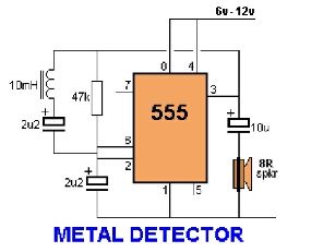
Assemble the circuit on a perfboard or PCB, excluding the inductor. Attach two long wires in place of the inductor. Use a long rod and position the inductor.
The circuit assembly begins with the preparation of a perfboard or printed circuit...
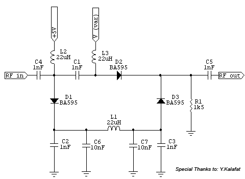
RF Signal Attenuator up to 30dB for 1MHz - 500MHz Input
This is a PIN diode-based RF signal attenuator circuit that operates with input frequencies ranging from 1 MHz to 500 MHz. PIN diodes are among the most commonly used components in RF applications.
The RF signal attenuator circuit utilizing PIN diodes...
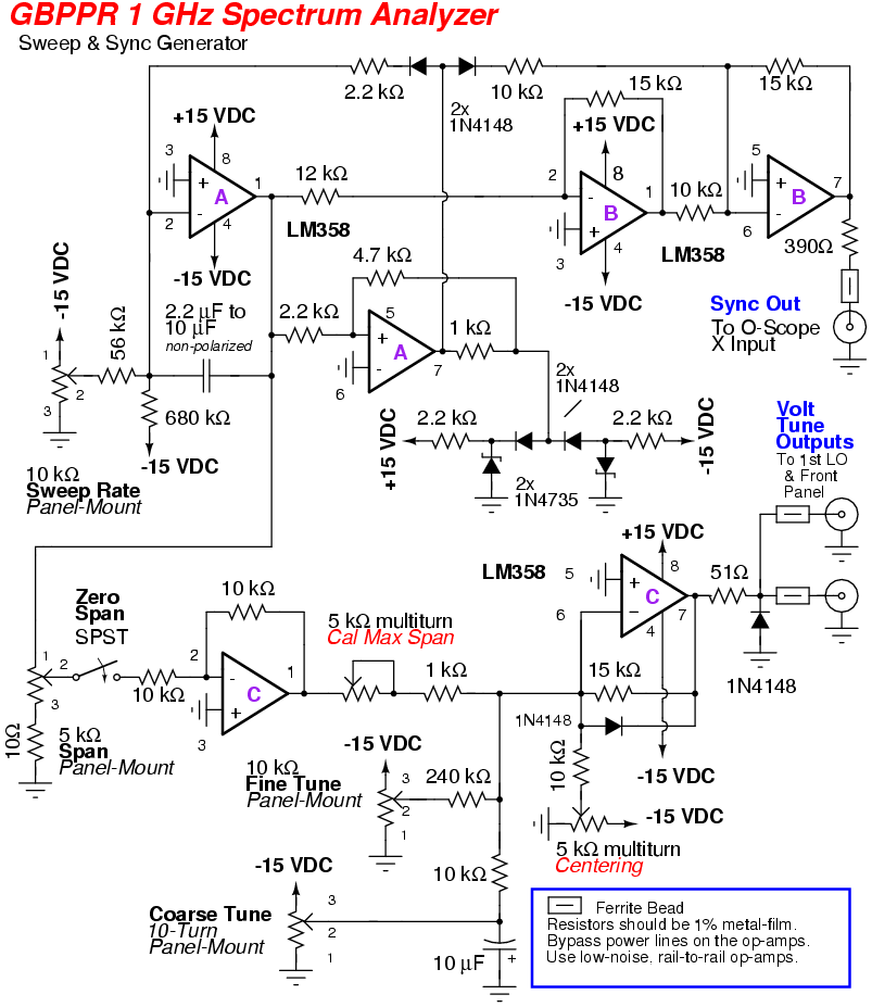
GBPPR 1 GHz RF Spectrum Analyzer
An RF spectrum analyzer is an essential tool for experimenters. The spectrum analyzer project described here is an enhancement of the "Spectrum Analyzer for the Radio Amateur" (Part 2) project by Wes Hayward (W7ZOI) and Terry White (K7TAU), which appeared...
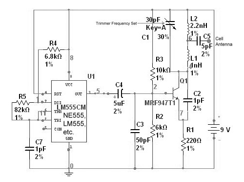
radio station blocker circuit
This device functions as a reversal of a radio station, sending a null signal to a selected frequency to eliminate the actual broadcast. The radio transmitter operates at a loss of 10,000W; therefore, this circuit is intended for use only...
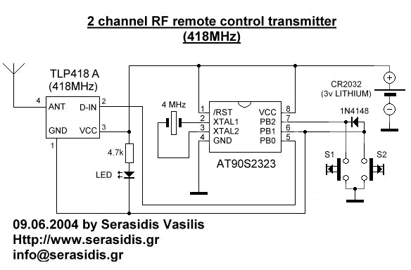
2 Channels RF remote control
Remote controls are often needed to manage various electric devices. There are several types of remote controls available, including infrared, RF (Radio Frequency), and SMS. Basic short-range remote controls primarily utilize infrared and RF technology. A limitation of infrared is...
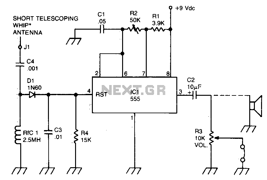
RF-powered sidetone oscillator
A sidetone oscillator is a specific type of audio astable multivibrator. Keying is achieved by turning the oscillator on and off through the application of a positive DC potential, which is generated from the RF signal to the reset terminal...
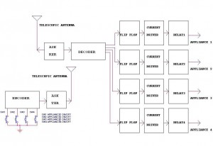
Remote ControlCircuit Through RF Without Microcontroller
This circuit illustrates a remote control circuit diagram using RF technology without the use of a microcontroller. Features include a simple remote control circuit that operates via radio frequency.
The remote control circuit operates by transmitting signals through radio waves, enabling...
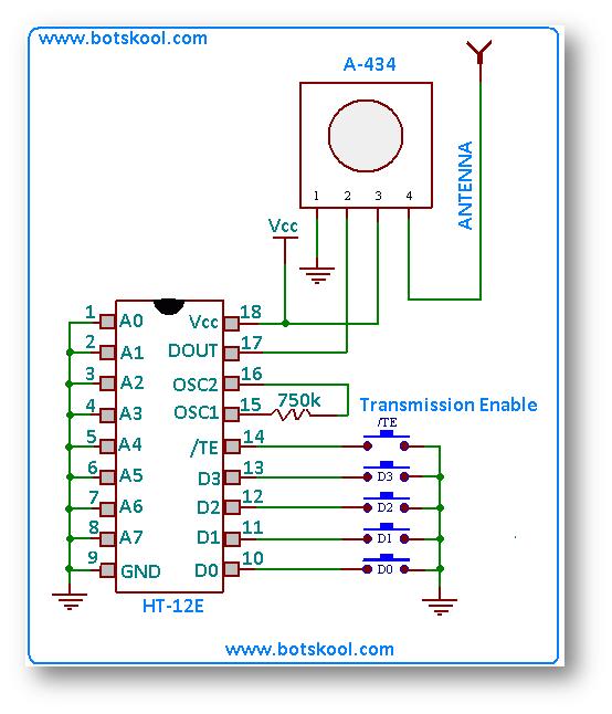
building rf remote control
The simplest approach to creating a remote-controlled robot is to repurpose a low-cost wireless toy car by removing its receiver module and remote control. Alternatively, one can design a custom RF remote using an ASK (Amplitude Shift Keying) based transmitter/receiver...