


kaizer sstc ii
#SSTC
#IRFP460
#MOSFET
#audio modulation
#full bridge
#RF
#Tesla coil
#high voltage
#driver board
#shielded drivers
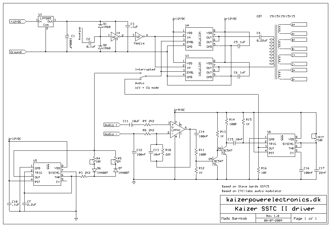
Description: This is a modified version of the first SSTC built, known as the Kaizer SSTC I. It utilizes the same secondary, topload, and driver board. New features include a full bridge made of IRFP460 MOSFETs, audio modulation, shielded drivers, and a new casing. Components were salvaged from a 19-inch LCD monitor and a 24-inch CRT monitor, including a piece of acrylic and a sizable heat sink. The acrylic was cut in half to create a two-level platform, while the heat sink was divided into four sections to isolate the MOSFETs, as their housing is conductive. The driver electronics and audio modulator are housed under a metal casing from the CRT monitor to shield against the strong electromagnetic field generated by the Tesla coil, preventing interference with the driver. The bridge consists of four IRFP460 MOSFETs, four MUR1560 diodes, and four 5-ohm resistors. The power supply features an 8A rectifier bridge and a BHC 1500 µF/450V smoothing capacitor, with a 27K 7W bleeder resistor added in the final assembly. The audio input jack was removed due to a short circuit caused by its metal housing connecting to the negative 12VDC rail, as the audio input's negative was not common with the negative 12VDC rail. The secondary is secured in place using a crate for ventilation, facilitating easy disassembly for transport or storage while providing a firm hold. With a 200 VAC input voltage, the system reaches 280 VDC on the bridge and consumes around 10A, peaking at 20A, resulting in a power draw between 2000 to 4000 Watts. This setup produces thick white arcs, demonstrating significant energy transfer, as evidenced by the relatively unharmed iPod shuffle subjected to the discharge. For sound input, a low-cost children's keyboard from a toy store is utilized, although it produces distorted waveforms rather than clean tones. Upgrading the SSTC I with a full bridge was essential, yielding improved performance, as the driver can effectively manage four MOSFETs instead of two. The coil can generate sparks up to 475mm in interrupted mode and white power arcs at 250mm, with the secondary winding measuring only 275mm in height. The full bridge configuration is understood to require four MOSFETs; however, a half bridge using a single MOSFET was also tested, showing comparable performance, albeit with slightly increased heat. The IRFP260 MOSFET can operate at lower bus voltages, rated for 200V, while the IRFP460 is rated for 500V. A minimum headroom of 30% is recommended, suggesting a maximum of 140VDC for a half bridge using IRFP260. The capacitors used for C8/C9 are 400VAC MKP X2 capacitors; any low ESR DC blocking capacitor with a higher voltage rating than the bus voltage can be used. The capacitor in series with the positive audio input should have its polarity correctly oriented, with the negative side connected to the audio signal input and the positive side to the 2K resistor. To operate the coil at higher voltages, it is necessary to decrease the primary-to-secondary coil coupling coefficient and ensure that all components can withstand the increased voltage. Achieving a high current with only 12V through the primary coil may require a very low primary impedance, possibly around half a turn.
The design and operation of the SSTC (Solid State Tesla Coil) rely heavily on the efficient management of high voltages and currents. The full bridge configuration of the IRFP460 MOSFETs allows for better control over the switching process, enhancing the overall performance and reliability of the system. The choice of MOSFETs is critical; the IRFP460's higher voltage rating makes it suitable for applications that demand robust performance under high-stress conditions.
The integration of audio modulation into the system allows for creative sound generation, although the quality of the sound is influenced by the waveform produced by the input device. The use of a children's keyboard, while cost-effective, may limit the fidelity of the output. However, it serves the purpose of providing an engaging interface for sound modulation.
The thermal management of the MOSFETs is addressed through the use of a heat sink, which is essential for maintaining operational stability and preventing overheating. The isolation of the MOSFETs from each other is a necessary precaution to avoid unintended conduction paths that could compromise the circuit's integrity.
The use of a metal casing for the driver electronics is a significant design feature, as it mitigates the effects of electromagnetic interference (EMI) generated by the Tesla coil. This shielding is vital for ensuring that the driver operates reliably without being affected by the high-frequency noise produced during operation.
The power supply design, featuring an 8A rectifier bridge and a large smoothing capacitor, provides the necessary energy storage to support the high power demands of the coil. The inclusion of a bleeder resistor ensures safe discharge of the capacitor when the system is powered down, enhancing safety during maintenance or adjustments.
Overall, the modified SSTC I demonstrates a sophisticated understanding of high-voltage electronics, component selection, and circuit design principles, resulting in a powerful and effective Tesla coil capable of producing impressive electrical discharges.This is a modified version of the first SSTC I built, the Kaizer SSTC I. It uses the same secondary, topload and driver board. New things is a full bridge of IRFP460 MOSFETs, audio modulation, shielded drivers and a new casing. I took apart a 19 ³ LCD monitor and a 24 ³ CRT monitor, from these respective computer parts I salvaged a good piece of acrylic from the LCD monitor and a fairly sized heat sink from the CRT. I cut the acrylic in half for a 2 level platform and the heat sink was cut in 4, its necessary to isolate the MOSFETs from each other as their housing is also a conductor. Driver electronics and audio modulator are installed under a metal casing from the CRT monitor to shield it from the heavy EM field surrounding the Tesla coil, this is to avoid problems with the driver being interrupted by its own EM field.
The bridge is made out of four IRFP460 MOSFETs, four MUR1560 diodes, four 5R resistors. The power supply is a 8A rectifier bridge with a BHC 1500 uF/450V smoothing capacitor, a 27K 7W bleeder resistor is added in the final build. The audio in jack was later removed due to it making a short through its metal housing to the negative 12VDC rail, I had overlooked that the audio in negative was not common with the negative 12VDC rail.
The secondary is held in place by a crate for ventilation on houses, its an easy and quick way of taking the coil apart for transport or storage, and it holds the secondary firm and tight. At 200 VAC input voltage, 280 VDC on the bridge and a power consumption around 10A, peaking at 20A, the coil was drawing somewhere in between 2000 to 4000 Watt.
This resulted in very hot, thick white arcs punishing the dead iPod shuffle which remarkably left the player relatively unharmed considered what had just taken place. For sound input I use a cheap children`s keyboard from a toy store, its far from perfect for the job, especially because its waveform is highly distorted and its not clean tones but seems to involve a lot of modulation inside it to simulate different instruments.
But its cheap and expendable. Upgrading the SSTC I with a full bridge was a absolute must. It is small changes compared to the better performance and the driver have no problems at all driving four MOSFETs instead of just two. Getting sparks at 475mm length in interrupted mode and white power arcs at 250mm length is truly satisfying for this little coil, the secondary winding itself is only 275mm in height in comparison.
I know how a full bridge works and I knew it takes four; I was talking about a half bridge, like the kaizer SSTC I. but useing a single Mosfet, I tryed it and it works just as good as two, ( but the Mosfet runs a little warmer).
1. IRFP260 will work at lower bus voltage, it is only rated for 200V where the IRFP460 is rated 500V, what is important is to keep a certain headroom, I would advise on atleast 30% headroom, so I would not apply more than 140VDC to a halfbridge of IRFP260. 2. The capacitors I used for C8/C9 are 400VAC MKP X2 capacitors, you can use any DC blocking low ESR capacitor as long as it has a higher voltage rating than your busvoltage.
The capacitor in series with the + audio input, is it`s polarity shown correctly negative side to the audio signal input (+) and positive side of the capactor to the 2K resistor To run this coil at higher voltages you should decrease the primary to secondary coil coupling coefficient and of course insure that all components can withstand the higher voltage. The thing is that with this topology you would need a very low primary impedance in order to get a current high enough with only 12 Volt through the primary, so a loose guess would be something half a turn .
If you want a low voltage Tesla c
The design and operation of the SSTC (Solid State Tesla Coil) rely heavily on the efficient management of high voltages and currents. The full bridge configuration of the IRFP460 MOSFETs allows for better control over the switching process, enhancing the overall performance and reliability of the system. The choice of MOSFETs is critical; the IRFP460's higher voltage rating makes it suitable for applications that demand robust performance under high-stress conditions.
The integration of audio modulation into the system allows for creative sound generation, although the quality of the sound is influenced by the waveform produced by the input device. The use of a children's keyboard, while cost-effective, may limit the fidelity of the output. However, it serves the purpose of providing an engaging interface for sound modulation.
The thermal management of the MOSFETs is addressed through the use of a heat sink, which is essential for maintaining operational stability and preventing overheating. The isolation of the MOSFETs from each other is a necessary precaution to avoid unintended conduction paths that could compromise the circuit's integrity.
The use of a metal casing for the driver electronics is a significant design feature, as it mitigates the effects of electromagnetic interference (EMI) generated by the Tesla coil. This shielding is vital for ensuring that the driver operates reliably without being affected by the high-frequency noise produced during operation.
The power supply design, featuring an 8A rectifier bridge and a large smoothing capacitor, provides the necessary energy storage to support the high power demands of the coil. The inclusion of a bleeder resistor ensures safe discharge of the capacitor when the system is powered down, enhancing safety during maintenance or adjustments.
Overall, the modified SSTC I demonstrates a sophisticated understanding of high-voltage electronics, component selection, and circuit design principles, resulting in a powerful and effective Tesla coil capable of producing impressive electrical discharges.This is a modified version of the first SSTC I built, the Kaizer SSTC I. It uses the same secondary, topload and driver board. New things is a full bridge of IRFP460 MOSFETs, audio modulation, shielded drivers and a new casing. I took apart a 19 ³ LCD monitor and a 24 ³ CRT monitor, from these respective computer parts I salvaged a good piece of acrylic from the LCD monitor and a fairly sized heat sink from the CRT. I cut the acrylic in half for a 2 level platform and the heat sink was cut in 4, its necessary to isolate the MOSFETs from each other as their housing is also a conductor. Driver electronics and audio modulator are installed under a metal casing from the CRT monitor to shield it from the heavy EM field surrounding the Tesla coil, this is to avoid problems with the driver being interrupted by its own EM field.
The bridge is made out of four IRFP460 MOSFETs, four MUR1560 diodes, four 5R resistors. The power supply is a 8A rectifier bridge with a BHC 1500 uF/450V smoothing capacitor, a 27K 7W bleeder resistor is added in the final build. The audio in jack was later removed due to it making a short through its metal housing to the negative 12VDC rail, I had overlooked that the audio in negative was not common with the negative 12VDC rail.
The secondary is held in place by a crate for ventilation on houses, its an easy and quick way of taking the coil apart for transport or storage, and it holds the secondary firm and tight. At 200 VAC input voltage, 280 VDC on the bridge and a power consumption around 10A, peaking at 20A, the coil was drawing somewhere in between 2000 to 4000 Watt.
This resulted in very hot, thick white arcs punishing the dead iPod shuffle which remarkably left the player relatively unharmed considered what had just taken place. For sound input I use a cheap children`s keyboard from a toy store, its far from perfect for the job, especially because its waveform is highly distorted and its not clean tones but seems to involve a lot of modulation inside it to simulate different instruments.
But its cheap and expendable. Upgrading the SSTC I with a full bridge was a absolute must. It is small changes compared to the better performance and the driver have no problems at all driving four MOSFETs instead of just two. Getting sparks at 475mm length in interrupted mode and white power arcs at 250mm length is truly satisfying for this little coil, the secondary winding itself is only 275mm in height in comparison.
I know how a full bridge works and I knew it takes four; I was talking about a half bridge, like the kaizer SSTC I. but useing a single Mosfet, I tryed it and it works just as good as two, ( but the Mosfet runs a little warmer).
1. IRFP260 will work at lower bus voltage, it is only rated for 200V where the IRFP460 is rated 500V, what is important is to keep a certain headroom, I would advise on atleast 30% headroom, so I would not apply more than 140VDC to a halfbridge of IRFP260. 2. The capacitors I used for C8/C9 are 400VAC MKP X2 capacitors, you can use any DC blocking low ESR capacitor as long as it has a higher voltage rating than your busvoltage.
The capacitor in series with the + audio input, is it`s polarity shown correctly negative side to the audio signal input (+) and positive side of the capactor to the 2K resistor To run this coil at higher voltages you should decrease the primary to secondary coil coupling coefficient and of course insure that all components can withstand the higher voltage. The thing is that with this topology you would need a very low primary impedance in order to get a current high enough with only 12 Volt through the primary, so a loose guess would be something half a turn .
If you want a low voltage Tesla c

Solid-State Tesla Coil 2
Tesla constructed the world's most powerful radio transmitter. Surrounding the base of a 200-foot mast, he installed an air-core transformer that measured 75 feet in diameter. The primary winding consisted of only a few turns of wire, while the secondary...
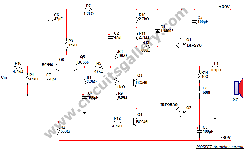
50 watt power MOSFET amplifier circuit diagram
This is a MOSFET transistor-based power amplifier circuit that operates within a voltage range of +35V to -35V. The input voltage is pre-filtered and pre-amplified before being applied to the MOSFET switch. The pre-audio amplifier consists of a differential amplifier...
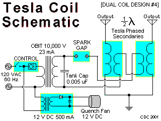
DUAL TESLA COIL
This area illustrates the construction and testing of a new half-wave (dual) Tesla coil. This type of coil features two secondaries driven by a single tank circuit. The design presented is a small and relatively inefficient dual coil constructed from...

Tesla HV Coil
When operated through a spark gap, does a Tesla coil always operate at a quarter wave, half wave, or a multiple of a whole wave, resulting in 2*n maximums? Are there sources related to creating standing waves and the resonance...
Singing Tesla Coil
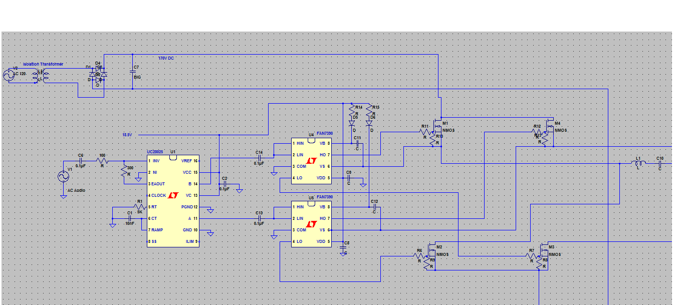
A Singing Tesla Coil is being developed for a 4-H electricity project, and the initial draft of the circuitry has been completed.
The Singing Tesla Coil is an innovative device that produces high-voltage, high-frequency alternating current (AC) electricity, resulting in visual...
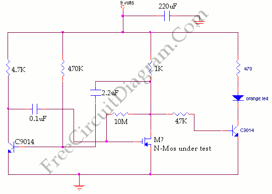
Mosfet Tester
This circuit falls under the category of an astable multivibrator. It is designed to test N-channel MOSFETs, specifically power types such as the IRF830, to determine their functionality.
The astable multivibrator circuit is a type of oscillator that continuously switches between...
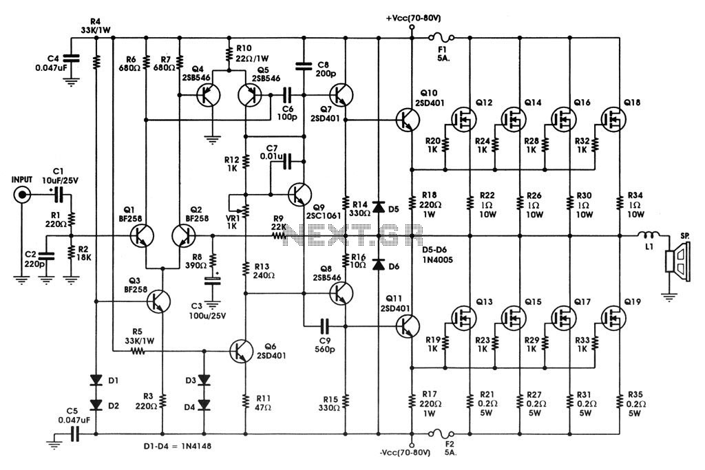
400 W MOSFET Audio Amplifier circuit using IRFP448 Diagram
400 W MOSFET Audio Amplifier circuit using IRFP448. This circuit is categorized under amplifiers and includes five circuit diagrams. For more detailed information, refer to the main post titled "400 W MOSFET Audio Amplifier Using IRFP448." This post also provides...
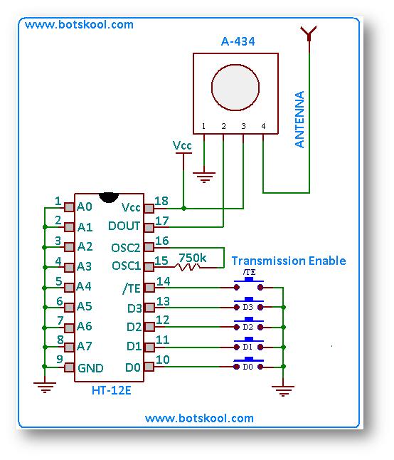
building rf remote control
The simplest approach to creating a remote-controlled robot is to repurpose a low-cost wireless toy car by removing its receiver module and remote control. Alternatively, one can design a custom RF remote using an ASK (Amplitude Shift Keying) based transmitter/receiver...
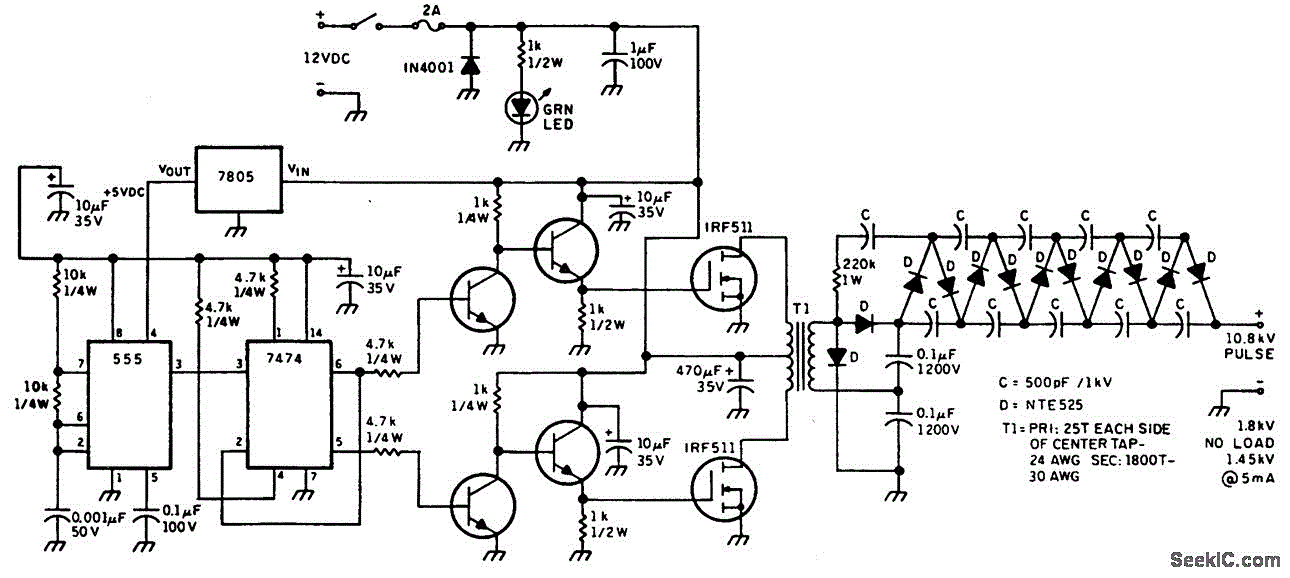
HELIUM NEON LASER SUPPLY
This figure illustrates a method for generating a momentary 10-kV voltage pulse to initiate plasma discharge across a laser tube. A diode voltage-multiplier circuit is connected in series with the main supply, obtaining its input power from one of the...