


Low-Frequency Prescaler
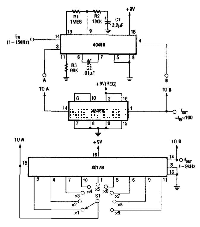
Description: For multiplying frequencies in the 1 to 150 Hz range, this circuit utilizes a 4046B phase-locked loop (PLL) and a 100 prescaler. The output from the voltage-controlled oscillator (VCO) is phase-locked to the low-frequency input. This configuration facilitates the use of a frequency counter to measure low-frequency signal frequencies. Additionally, by incorporating a 4017B decade counter and a 1 kHz clock signal, the circuit can function as a 1 to 9 kHz frequency synthesizer or as a x10 frequency multiplier.
The circuit operates primarily using the 4046B, which is a versatile PLL integrated circuit. The PLL configuration allows for precise frequency multiplication by maintaining a constant phase relationship between the input signal and the VCO output. The 100 prescaler reduces the frequency of the input signal, enabling the 4046B to effectively manage lower frequencies within its operational limits.
The VCO within the 4046B generates an output frequency that is determined by the control voltage applied to it. This output is then phase-locked to the incoming low-frequency signal, ensuring that the output frequency is a multiple of the input frequency. The phase comparator within the 4046B adjusts the control voltage based on the phase difference between the input signal and the VCO output, achieving stable frequency multiplication.
The subsequent stage utilizes a 4017B decade counter, which is designed to count pulses and can divide the frequency output from the VCO. By applying a 1 kHz clock signal to the 4017B, the circuit can generate a range of output frequencies from 1 kHz to 9 kHz, depending on the count configuration. This flexibility allows the circuit to be used not only as a frequency multiplier but also as a synthesizer, producing various frequency outputs for different applications.
In summary, the combination of the 4046B PLL, a prescaler, and the 4017B counter creates a robust circuit capable of frequency multiplication and synthesis over a specified range. This design is particularly useful in applications requiring precise frequency measurements and signal generation in the low-frequency domain. For multiplying frequencies in the 1-to 150-Hz range, this circuit uses a 4046B and a 100 prescaler. The VCO output is phaselocked to the low-frequency input. This simplifies use of a frequency counter to measure LF signal frequencies. By using a 4017B and a 1-kHz. the circuit can be used as a 1-to 9-kHz frequency synthesizer or as a x10 frequency multiplier.
The circuit operates primarily using the 4046B, which is a versatile PLL integrated circuit. The PLL configuration allows for precise frequency multiplication by maintaining a constant phase relationship between the input signal and the VCO output. The 100 prescaler reduces the frequency of the input signal, enabling the 4046B to effectively manage lower frequencies within its operational limits.
The VCO within the 4046B generates an output frequency that is determined by the control voltage applied to it. This output is then phase-locked to the incoming low-frequency signal, ensuring that the output frequency is a multiple of the input frequency. The phase comparator within the 4046B adjusts the control voltage based on the phase difference between the input signal and the VCO output, achieving stable frequency multiplication.
The subsequent stage utilizes a 4017B decade counter, which is designed to count pulses and can divide the frequency output from the VCO. By applying a 1 kHz clock signal to the 4017B, the circuit can generate a range of output frequencies from 1 kHz to 9 kHz, depending on the count configuration. This flexibility allows the circuit to be used not only as a frequency multiplier but also as a synthesizer, producing various frequency outputs for different applications.
In summary, the combination of the 4046B PLL, a prescaler, and the 4017B counter creates a robust circuit capable of frequency multiplication and synthesis over a specified range. This design is particularly useful in applications requiring precise frequency measurements and signal generation in the low-frequency domain. For multiplying frequencies in the 1-to 150-Hz range, this circuit uses a 4046B and a 100 prescaler. The VCO output is phaselocked to the low-frequency input. This simplifies use of a frequency counter to measure LF signal frequencies. By using a 4017B and a 1-kHz. the circuit can be used as a 1-to 9-kHz frequency synthesizer or as a x10 frequency multiplier.
Whooper
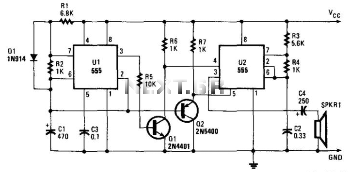
The integrated circuit U1 is configured as a low-frequency asymmetrical oscillator. Its output is inverted by Q1 and sent to the reset terminal of U2 at pin 5. Integrated circuit U2 operates as an audio oscillator and is activated when...
Timer circuit
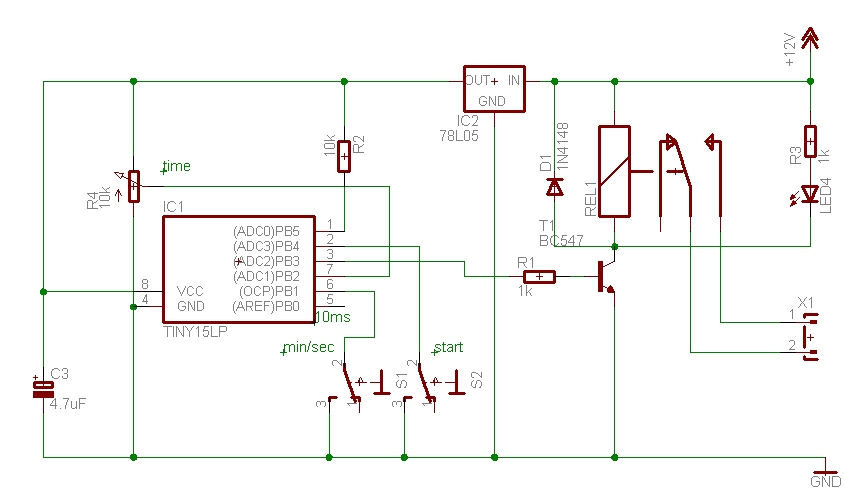
The time can be set using a potentiometer ranging from 1 minute to 1023 minutes, approximately 17 hours. A pushbutton initiates the timing process, activates a relay, and the timer will deactivate the relay once the set time has elapsed....
Simple-vco
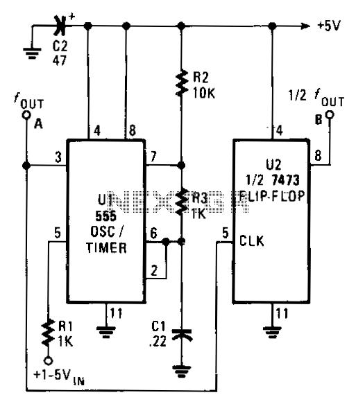
The output frequency of the voltage-controlled oscillator (VCO), U1, varies inversely with the input voltage. With a 1 V input, the oscillator output frequency is approximately 1500 Hz; with a 5 V input, the output frequency decreases to around 300...
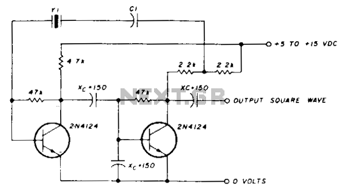
Low-frequency oscillator 10-150khz
A capacitor in series with the crystal may be utilized to adjust the oscillator output frequency. The value may range between 20 pF and 0.01 µF, or it may be a trimmer capacitor, and it will approximately equal the crystal...
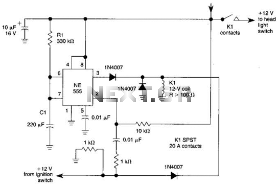
Automatic Turn-Off Control For Automobiles Circuit
When the ignition switch is activated, relay K1 receives continuous power, allowing the headlights to be turned on. When the ignition is turned off, timer IC1 is activated, maintaining its power for a duration determined by resistor R1 and capacitor...
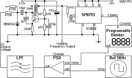
SYNTHESIZER BASICS
This is a programmable frequency multiplier that typically utilizes digital logic integrated circuits. The synthesizer is designed to multiply a reference frequency by a programmable factor to achieve virtually any desired frequency. For instance, with a reference frequency of 1...
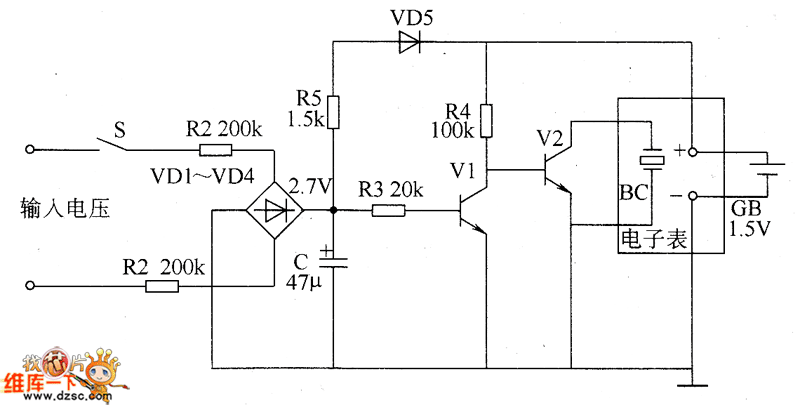
Cumulative timer circuit diagram
The cumulative timer circuit comprises resistor R1 and an internal crystal oscillator, represented in a chart. Resistors R1 and R2 are metal film types, while resistors R3 to R5 are rated at 1/8W and also of the metal film variety....
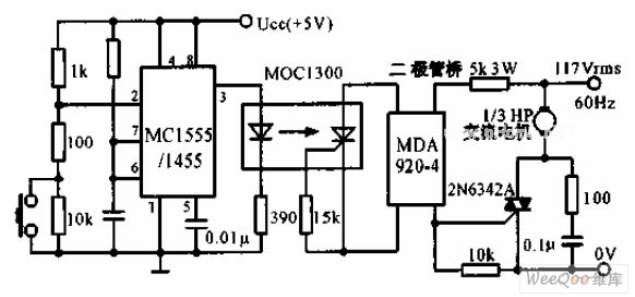
The switch shut off time delay circuit diagram
The switch shut-off time delay circuit consists of a timer, optocouplers, a bridge SCR, and an SCR AC switch. When the control button is released, it allows the motor or other AC power to remain active for one hour. Upon...
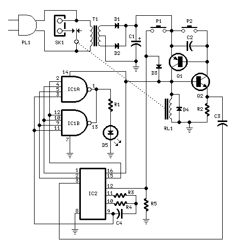
Bedside Lamp Timers
The objective of this circuit is to power a lamp or other device for a predetermined duration (30 minutes in this instance) and subsequently turn it off. This functionality is particularly beneficial for reading in bed at night, as it...