


low frequency sinewave
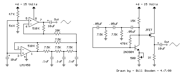
Description: The two circuits below illustrate the generation of low-frequency sine waves by shifting the phase of the signal through an RC network, ensuring that oscillation occurs when the total phase shift reaches 360 degrees. The transistor circuit on the right produces a reasonable sine wave at the collector of the 3904 transistor, which is buffered by a JFET to yield a low impedance output. The circuit gain is critical for minimizing distortion, and it may be necessary to adjust the 500-ohm resistor to achieve a stable waveform with minimal distortion. However, the transistor circuit is not recommended for practical applications due to the critical adjustments required. In contrast, the op-amp-based phase shift oscillator is significantly more stable than the single transistor version, as the gain can be set higher than necessary to sustain oscillation. The output is taken from the RC network, which effectively filters out most harmonic distortion. The sine wave output from the RC network is buffered, and the amplitude is restored by the second (top) op-amp, which has a gain of approximately 28 dB. The frequency is around 600 Hz for the specified RC values (7.5 kΩ and 0.1 µF) and can be reduced by proportionally increasing the network resistors (7.5 kΩ). The 7.5 kΩ resistor at pin 2 of the op-amp controls the oscillator circuit gain and is selected to ensure that the output at pin 1 is slightly clipped at both the positive and negative peaks. The sine wave output at pin 7 is approximately 5 volts peak-to-peak when using a 12-volt supply, and it appears very clean on an oscilloscope, as the RC network filters out nearly all distortion occurring at pin 1.
The described circuits utilize two distinct methods for generating low-frequency sine waves. The first method employs a transistor-based oscillator, which relies on a 3904 transistor configured to produce a sine wave output. This circuit requires careful tuning of the gain, facilitated by a 500-ohm resistor, to achieve a stable output with minimal distortion. However, the sensitivity of this design to component variations and adjustments limits its practical application.
In contrast, the op-amp-based phase shift oscillator offers a more robust solution. This design consists of a series of RC networks that achieve the necessary phase shifts for oscillation. The op-amp's gain can be easily adjusted to exceed the minimum threshold needed for oscillation, enhancing stability and reducing the likelihood of distortion. The output derived from the RC network is buffered by a second op-amp, which not only restores the amplitude but also ensures a clean sine wave output.
The frequency of oscillation is determined by the values of the resistors and capacitors in the RC network. In this configuration, a 7.5 kΩ resistor in conjunction with a 0.1 µF capacitor yields a frequency of approximately 600 Hz. By increasing the resistance values proportionally, the frequency can be lowered, providing flexibility in application. The careful selection of components, particularly the 7.5 kΩ resistor at pin 2 of the op-amp, ensures that the output waveform remains within acceptable limits, avoiding excessive clipping and distortion.
Overall, the op-amp-based phase shift oscillator is favored for applications requiring low distortion and high stability, making it suitable for various electronic signal processing tasks. The clean sine wave output, capable of achieving around 5 volts peak-to-peak with a 12-volt supply, is an advantage that enhances its usability in practical circuits.The two circuits below illustrate generating low frequency sinewaves by shifting the phase of the signal through an RC network so that oscillation occurs where the total phase shift is 360 degrees. The transistor circuit on the right produces a reasonable sinewave at the collector of the 3904 which is buffered by the JFET to yield a low impedance
output. The circuit gain is critical for low distortion and you may need to adjust the 500 ohm resistor to achieve a stable waveform with minimum distortion. The transistor circuit is not recommended for practical applications due to the critical adjustments needed.
The op-amp based phase shift oscillator is much more stable than the single transistor version since the gain can be set higher than needed to sustain oscillation and the output is taken from the RC network which filters out most of the harmonic distortion. The sinewave output from the RC network is buffered and the amplitude restored by the second (top) op-amp which has gain of around 28dB.
Frequency is around 600 Hz for RC values shown (7. 5K and 0. 1uF) and can be reduced by proportionally increasing the network resistors (7. 5K). The 7. 5K value at pin 2 of the op-amp controls the oscillator circuit gain and is selected so that the output at pin 1 is slightly clipped at the positive and negative peaks. The sinewave output at pin 7 is about 5 volts p-p using a 12 volt supply and appears very clean on a scope since the RC network filters out most all distortion occurring at pin 1.
The described circuits utilize two distinct methods for generating low-frequency sine waves. The first method employs a transistor-based oscillator, which relies on a 3904 transistor configured to produce a sine wave output. This circuit requires careful tuning of the gain, facilitated by a 500-ohm resistor, to achieve a stable output with minimal distortion. However, the sensitivity of this design to component variations and adjustments limits its practical application.
In contrast, the op-amp-based phase shift oscillator offers a more robust solution. This design consists of a series of RC networks that achieve the necessary phase shifts for oscillation. The op-amp's gain can be easily adjusted to exceed the minimum threshold needed for oscillation, enhancing stability and reducing the likelihood of distortion. The output derived from the RC network is buffered by a second op-amp, which not only restores the amplitude but also ensures a clean sine wave output.
The frequency of oscillation is determined by the values of the resistors and capacitors in the RC network. In this configuration, a 7.5 kΩ resistor in conjunction with a 0.1 µF capacitor yields a frequency of approximately 600 Hz. By increasing the resistance values proportionally, the frequency can be lowered, providing flexibility in application. The careful selection of components, particularly the 7.5 kΩ resistor at pin 2 of the op-amp, ensures that the output waveform remains within acceptable limits, avoiding excessive clipping and distortion.
Overall, the op-amp-based phase shift oscillator is favored for applications requiring low distortion and high stability, making it suitable for various electronic signal processing tasks. The clean sine wave output, capable of achieving around 5 volts peak-to-peak with a 12-volt supply, is an advantage that enhances its usability in practical circuits.The two circuits below illustrate generating low frequency sinewaves by shifting the phase of the signal through an RC network so that oscillation occurs where the total phase shift is 360 degrees. The transistor circuit on the right produces a reasonable sinewave at the collector of the 3904 which is buffered by the JFET to yield a low impedance
output. The circuit gain is critical for low distortion and you may need to adjust the 500 ohm resistor to achieve a stable waveform with minimum distortion. The transistor circuit is not recommended for practical applications due to the critical adjustments needed.
The op-amp based phase shift oscillator is much more stable than the single transistor version since the gain can be set higher than needed to sustain oscillation and the output is taken from the RC network which filters out most of the harmonic distortion. The sinewave output from the RC network is buffered and the amplitude restored by the second (top) op-amp which has gain of around 28dB.
Frequency is around 600 Hz for RC values shown (7. 5K and 0. 1uF) and can be reduced by proportionally increasing the network resistors (7. 5K). The 7. 5K value at pin 2 of the op-amp controls the oscillator circuit gain and is selected so that the output at pin 1 is slightly clipped at the positive and negative peaks. The sinewave output at pin 7 is about 5 volts p-p using a 12 volt supply and appears very clean on a scope since the RC network filters out most all distortion occurring at pin 1.
Simple Audio amplifier Using Transistors
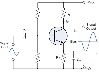
Construct a basic audio amplifier utilizing transistors. While integrated circuit (IC) designs are available for this purpose, the intention is to use transistors to gain practical knowledge about their amplification capabilities. The article "Amplifier Basics - How Amps Work (Intro)"...
Controlled Transistor Series Regulator With Overload and Short-Circuit Protection
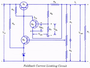
If the load resistance (RL) is reduced or the load terminals are accidentally shorted, a very large load current will flow, potentially damaging the pass transistor (Q1), diode, or other components. Fuse protection may not be sufficient, as the transistor...
The Transistor Amplifier-P2
The three circuits described provide a constant current to the LED (or LEDs) when the supply voltage reaches 15V or higher. The second and third circuits can be activated or deactivated through the input line by turning on the top...
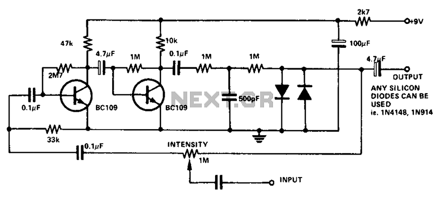
Boombox circuit diagram
The circuit utilizes a transistor to amplify the input signal. Two diodes are employed to clamp the distorted output, while a 500 pF capacitor filters out high-frequency noise. Under normal conditions, a 1M slide rheostat is used to adjust the...
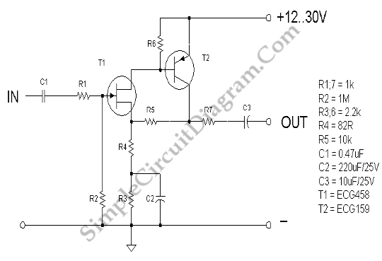
JFET Low Noise Preamp
Noise in an amplifier circuit is intrinsically generated by each component within the circuit. Resistors, capacitors, and semiconductors all contribute to noise generation.
Noise in an amplifier circuit can significantly affect performance and signal integrity. Each component, including resistors, capacitors, and...
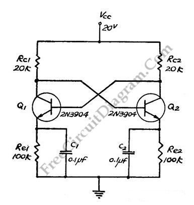
Direct Coupled Discrete Astable Multivibrator circuit
This flip-flop circuit functions as a free-running astable multivibrator, where the bases and collectors of both emitter-biased transistors are directly coupled. The switching action is facilitated by a capacitor in each emitter circuit, resulting in the generation of triangle waves...
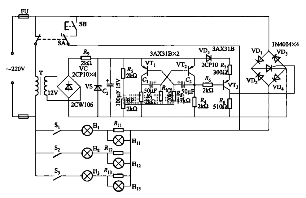
Ship Navigation lights circuit
The self-excited multivibrator circuit utilizes transistors VTi and VT2 to generate an output signal that triggers a thyristor (VT3). An adjustment potentiometer (RP) is incorporated to modify the oscillation frequency, which in turn adjusts the flashing cycles of lights Hi...

phase shift oscillator circuit
This design circuit features a simple, cost-effective amplitude-stabilized phase-shift sine wave oscillator that requires one integrated circuit (IC) package, three transistors, and operates from a single power supply. The circuit incorporates an RC network configured for phase shift, oscillating at...
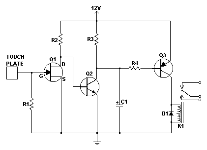
simple touch switch circuit
Similar to the CMOS-based touch switch available on this site, this transistor-based touch switch can activate a load simply by the user touching a metal plate. It is designed to directly switch a relay, allowing it to be used with...