


Non-sinusoidal oscillator circuit waveform pulse wave oscillator single-junction oscillator
#non-sinusoidal
#pulse wave
#single-junction transistor
#blocking oscillator
#waveform
#frequency formula
#transistor
#pulse generator
#electronic oscillator
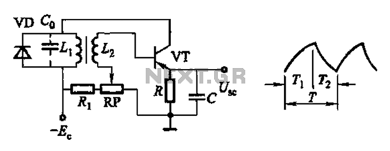
Description: Common non-sinusoidal oscillator circuit, waveform and frequency formula - pulse wave oscillator - single-junction transistor blocking oscillator.
The common non-sinusoidal oscillator circuit described is a pulse wave oscillator that utilizes a single-junction transistor in a blocking configuration. This type of oscillator is characterized by its ability to generate square or pulse waveforms, which are essential in various electronic applications such as timing circuits, clock generators, and signal modulators.
In a typical single-junction transistor blocking oscillator circuit, the transistor operates in a switching mode. When the circuit is powered, the transistor is initially turned off, preventing current from flowing through the collector-emitter path. A capacitor is connected to the base of the transistor, charging through a resistor. Once the voltage across the capacitor reaches a certain threshold, the transistor turns on, allowing current to flow and rapidly discharging the capacitor. This action produces a pulse in the output.
The frequency of the output waveform can be determined by the values of the resistor and capacitor used in the circuit, as well as the characteristics of the transistor. The basic formula for the frequency (f) of the oscillator is given by:
f = 1 / (2 * π * R * C)
where R is the resistance in ohms and C is the capacitance in farads. This formula indicates that the frequency is inversely proportional to both the resistance and capacitance values; thus, increasing either the resistance or capacitance will decrease the frequency of the oscillation.
The waveform produced by this oscillator is typically a square wave, which can be further manipulated with additional components to achieve desired characteristics such as duty cycle and amplitude. The simplicity and effectiveness of the single-junction transistor blocking oscillator make it a popular choice in various electronic designs that require pulse generation. Common non-sinusoidal oscillator circuit, waveform and frequency formula - pulse wave oscillator - single-junction transistor blocking oscillator
The common non-sinusoidal oscillator circuit described is a pulse wave oscillator that utilizes a single-junction transistor in a blocking configuration. This type of oscillator is characterized by its ability to generate square or pulse waveforms, which are essential in various electronic applications such as timing circuits, clock generators, and signal modulators.
In a typical single-junction transistor blocking oscillator circuit, the transistor operates in a switching mode. When the circuit is powered, the transistor is initially turned off, preventing current from flowing through the collector-emitter path. A capacitor is connected to the base of the transistor, charging through a resistor. Once the voltage across the capacitor reaches a certain threshold, the transistor turns on, allowing current to flow and rapidly discharging the capacitor. This action produces a pulse in the output.
The frequency of the output waveform can be determined by the values of the resistor and capacitor used in the circuit, as well as the characteristics of the transistor. The basic formula for the frequency (f) of the oscillator is given by:
f = 1 / (2 * π * R * C)
where R is the resistance in ohms and C is the capacitance in farads. This formula indicates that the frequency is inversely proportional to both the resistance and capacitance values; thus, increasing either the resistance or capacitance will decrease the frequency of the oscillation.
The waveform produced by this oscillator is typically a square wave, which can be further manipulated with additional components to achieve desired characteristics such as duty cycle and amplitude. The simplicity and effectiveness of the single-junction transistor blocking oscillator make it a popular choice in various electronic designs that require pulse generation. Common non-sinusoidal oscillator circuit, waveform and frequency formula - pulse wave oscillator - single-junction transistor blocking oscillator
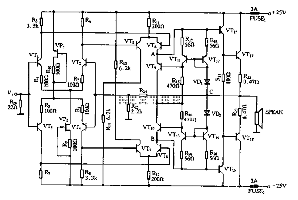
Full complementary symmetry amplifier CL
The CL type circuit is not a power amplifier output capacitance, feedback capacitance, or compensation capacitor amplifier circuit; it operates solely through a transistor (or FET) and a resistor. This circuit can generate feedback, and phase shift elements are omitted....
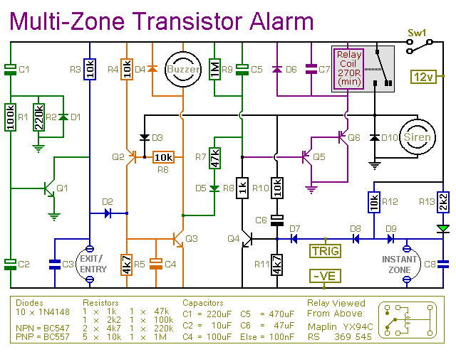
Multi-Zone Transistor-Based Intruder Alarm
This is a simple transistor-based burglar alarm circuit. Its features include automatic exit and entry delays, along with a timed bell cut-off and reset. It is designed to be used with standard types of normally-closed input devices such as magnetic...
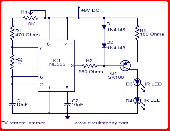
kode kunci satu transistor
This is the simplest electronic code lock circuit that can be constructed. The circuit utilizes one transistor, a relay, and a few passive components. Its simplicity does not compromise performance, as the circuit operates effectively. Essentially, it functions as a...
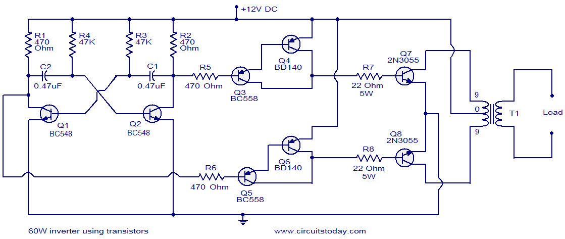
60W inverter using transistors
This circuit diagram illustrates a fully transistorized inverter capable of driving loads of up to 60W. Transistors Q1 and Q2 create a 50Hz astable multivibrator. The output from the collector of Q2 connects to the input of a Darlington pair...
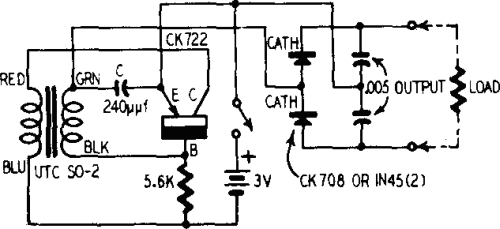
Transistor DC Transformer
A battery is a low-impedance power source. It operates most efficiently and economically when providing low voltage at high current.
Batteries serve as essential components in various electronic circuits, functioning as a reliable source of energy. Their low-impedance characteristic allows for...
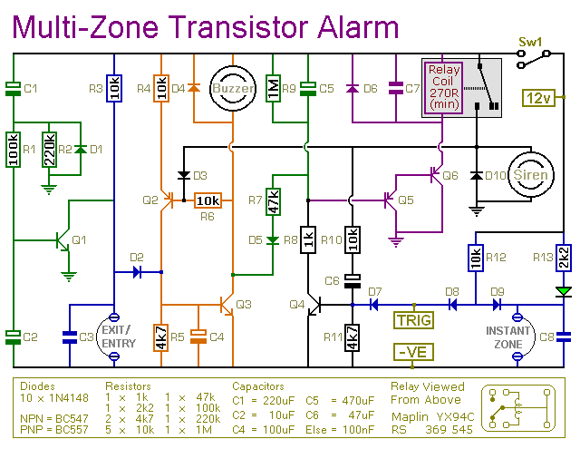
transistor based burglar alarm
This is a simple transistor-based burglar alarm circuit. Its features include automatic exit and entry delays, along with a timed bell cut-off and reset. It is designed to be used with common types of normally-closed input devices such as magnetic-reed...
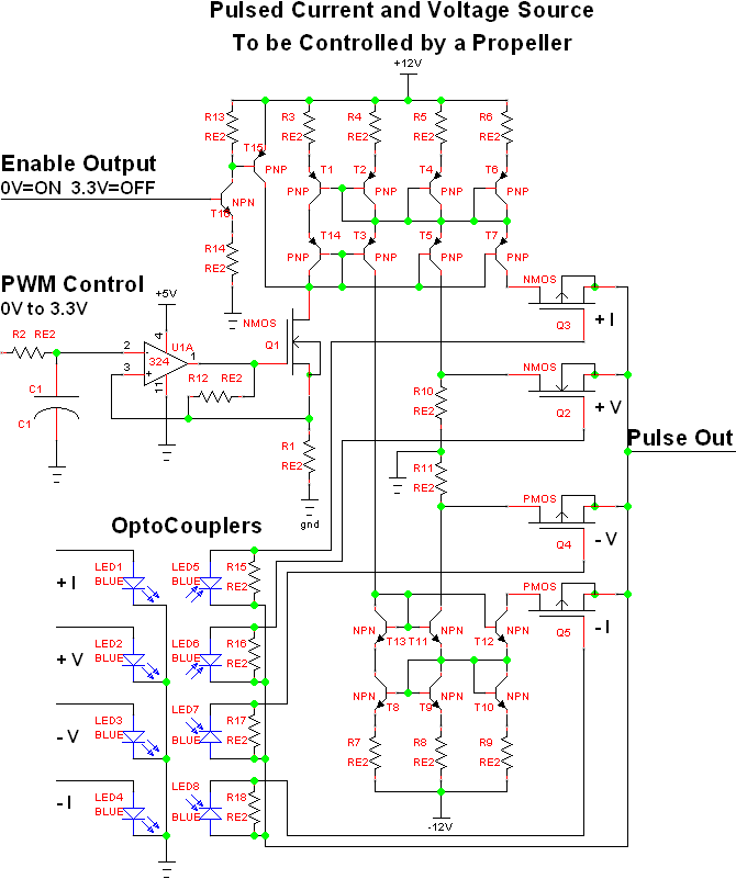
Full on transistor/fet curve tracer
The project involves adapting a curve tracer schematic, likely based on Metzger's circuit from the early 1970s, to integrate an ADC capture system and output the data to a 320x256 ELD panel. Additionally, a serial output will be included to...
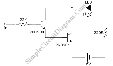
Darlington Transistor Pair Logic Probe
Ideally, any testing equipment will not draw any current from the device under test. This ideal condition can be approximated by designing a testing device.
To achieve the ideal condition where testing equipment does not draw current from the device under...
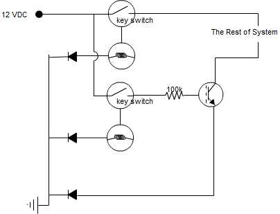
transistor as a switch circuit problems
A circuit is being designed that incorporates two key switches, which must both be closed for current to flow through the circuit.
The proposed circuit configuration employs two key switches connected in series. In this arrangement, the current can only pass...