


Operation of an Pierce Oscillator
#Pierce Oscillator
#crystal oscillator
#PNP transistor
#tank circuit
#resonant circuit
#frequency generation
#electronics
#circuit design
#signal generation
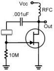
Description: A Pierce Oscillator is a type of oscillator that utilizes a crystal instead of a parallel-resonant circuit (LC circuit). This oscillator also employs the voltage developed from a tap between two capacitors in the tank circuit. Both Pierce Oscillators use a PNP transistor as the amplifier. Any PNP transistor may be used, provided it exhibits gain at the desired frequency of operation. Two common general-purpose PNP transistors are the 2N3904 and 2N3906, both of which offer frequency operation exceeding 100 MHz. The critical criterion is that the transistor must provide amplification within the frequency range of oscillation. The circuits are quite similar. The DC voltage is supplied by Vcc, which is set within the range suitable for the selected transistor. For instance, the 2N3904 has a maximum Collector-Base voltage of 60 volts and a maximum Collector-Emitter voltage of 40 volts. The DC bias currents are established by several resistors. Resistor Re determines the emitter current, while resistor Rc sets the collector current. The base voltage is established by a voltage divider formed by resistors Rf and Rb, calculated as Vcc x Rb/(Rb + Rf).
The Pierce Oscillator is an essential component in various electronic applications, particularly in frequency generation and signal processing. It operates by leveraging the piezoelectric properties of the crystal, which provides precise frequency stability. The oscillator circuit typically consists of a PNP transistor, a crystal, and a tank circuit formed by capacitors and resistors.
In a typical configuration, the PNP transistor is biased to operate in the active region, allowing it to amplify the oscillations. The crystal is connected in the feedback loop, which ensures that the oscillator operates at its fundamental frequency. The tank circuit, composed of two capacitors, creates a resonant circuit that enhances the stability and purity of the oscillation frequency.
The choice of the PNP transistor is critical, as it must be capable of providing sufficient gain at the desired operating frequency. The 2N3904 and 2N3906 are popular choices due to their high-frequency performance and availability. The resistors in the circuit must be selected carefully to ensure proper biasing of the transistor, which is crucial for maintaining stable oscillation.
The voltage divider formed by resistors Rf and Rb is responsible for setting the base voltage of the transistor. This configuration allows for fine-tuning of the oscillator's frequency and amplitude. The overall design must ensure that the supply voltage (Vcc) is within the operational limits of the chosen transistor to prevent damage and ensure reliable operation.
In summary, the Pierce Oscillator is a versatile and widely used circuit in electronics, providing high-frequency oscillation with excellent stability. Its design involves careful selection of components and precise calculations to achieve the desired performance characteristics.A Pierce Oscillator is a type of oscillator that uses a crystal instead of a parallel-resonant circuit [LC circuit]. A pierce oscillator also uses the voltage developed from a tap between two capacitors in the tank circuit, as shown to the right.
range. Both of the Pierce Oscillators use a PNP transistor as the amplifier. Basically any PNP transis tor may be used as long as it exhibits gain at the desired frequency of operation. Two common general purpose PNP transistors include the 2N3904 PNP Transistor and 2N3906 PNP Transistor. Both of these transistors offer frequency operation over 100MHz. The important criteria is that the transistor provides amplification in the frequency range of oscillation.
Both of these circuits are very similar. The DC voltage is supplied by Vcc, set to be in range of the transistor selected. The 2N3904, for example, has a maximum Collector-Base voltage of 60 volts and Collector-Emitter voltage of 40 volts. The DC bias currents are set by a number of resistors. Resistor Re sets the emitter current. The collector current is set by resistor Rc. The Base voltage is set by the voltage divider formed by resistors Rf and Rb and is equal to Vcc x Rb/(Rb + Rf)].
The Pierce Oscillator is an essential component in various electronic applications, particularly in frequency generation and signal processing. It operates by leveraging the piezoelectric properties of the crystal, which provides precise frequency stability. The oscillator circuit typically consists of a PNP transistor, a crystal, and a tank circuit formed by capacitors and resistors.
In a typical configuration, the PNP transistor is biased to operate in the active region, allowing it to amplify the oscillations. The crystal is connected in the feedback loop, which ensures that the oscillator operates at its fundamental frequency. The tank circuit, composed of two capacitors, creates a resonant circuit that enhances the stability and purity of the oscillation frequency.
The choice of the PNP transistor is critical, as it must be capable of providing sufficient gain at the desired operating frequency. The 2N3904 and 2N3906 are popular choices due to their high-frequency performance and availability. The resistors in the circuit must be selected carefully to ensure proper biasing of the transistor, which is crucial for maintaining stable oscillation.
The voltage divider formed by resistors Rf and Rb is responsible for setting the base voltage of the transistor. This configuration allows for fine-tuning of the oscillator's frequency and amplitude. The overall design must ensure that the supply voltage (Vcc) is within the operational limits of the chosen transistor to prevent damage and ensure reliable operation.
In summary, the Pierce Oscillator is a versatile and widely used circuit in electronics, providing high-frequency oscillation with excellent stability. Its design involves careful selection of components and precise calculations to achieve the desired performance characteristics.A Pierce Oscillator is a type of oscillator that uses a crystal instead of a parallel-resonant circuit [LC circuit]. A pierce oscillator also uses the voltage developed from a tap between two capacitors in the tank circuit, as shown to the right.
range. Both of the Pierce Oscillators use a PNP transistor as the amplifier. Basically any PNP transis tor may be used as long as it exhibits gain at the desired frequency of operation. Two common general purpose PNP transistors include the 2N3904 PNP Transistor and 2N3906 PNP Transistor. Both of these transistors offer frequency operation over 100MHz. The important criteria is that the transistor provides amplification in the frequency range of oscillation.
Both of these circuits are very similar. The DC voltage is supplied by Vcc, set to be in range of the transistor selected. The 2N3904, for example, has a maximum Collector-Base voltage of 60 volts and Collector-Emitter voltage of 40 volts. The DC bias currents are set by a number of resistors. Resistor Re sets the emitter current. The collector current is set by resistor Rc. The Base voltage is set by the voltage divider formed by resistors Rf and Rb and is equal to Vcc x Rb/(Rb + Rf)].
Fishermans Dipper
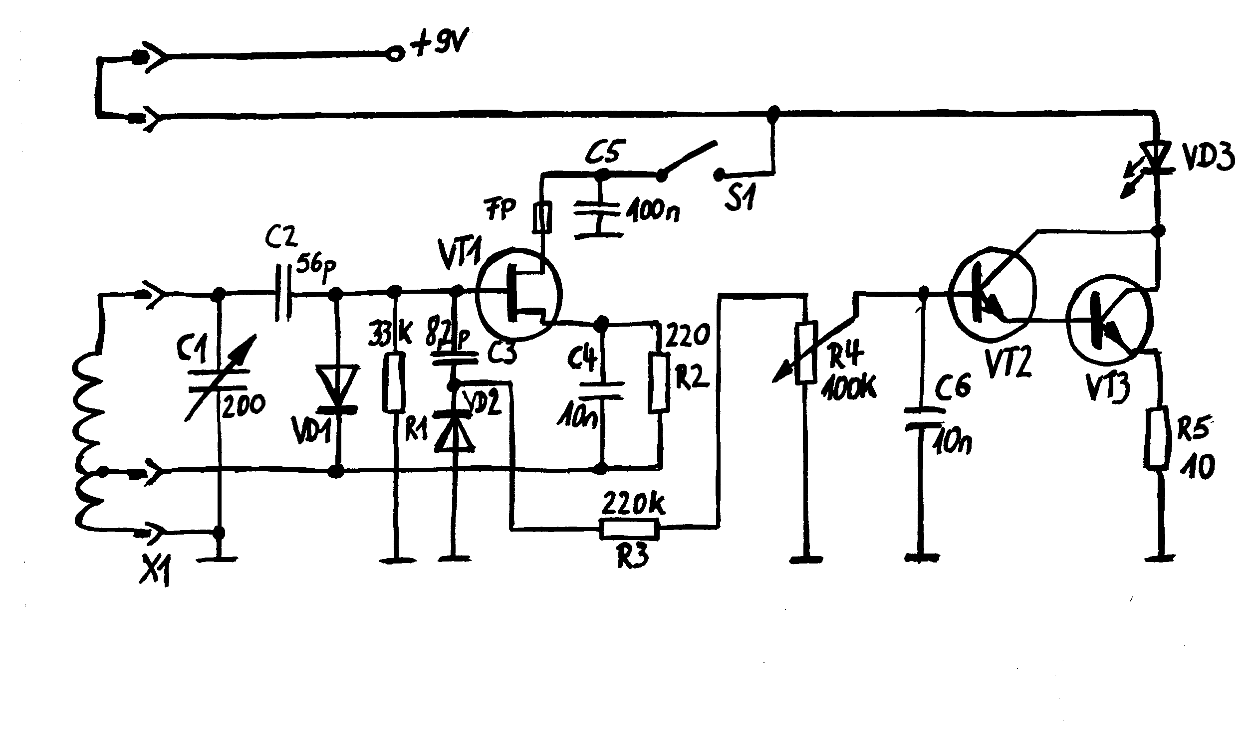
The measuring resonant circuit, while actively operating, is loosely coupled to the resonant circuit of the dipper, meaning it is brought close to it. The dipper is tuned from the lowest to the highest frequency. When the dipper and the...
Crystal Oscillator Circuit
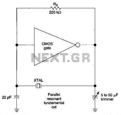
The CMOS amplifier is biased into the linear region by resistor RB. The pi-type crystal network (C1 and C2, and XTAL) provides the 180-degree phase shift at the resonant frequency, which causes the circuit to oscillate.
The described circuit utilizes a...
Checking out the Pierce oscillator
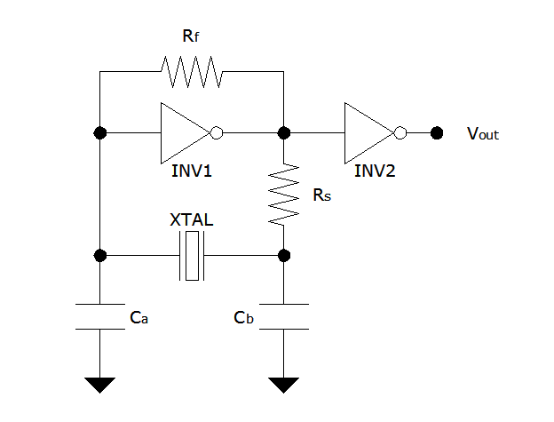
The Pierce oscillator is a simple circuit that, like the ring oscillator, utilizes inverters, though typically only one inverter is required. Its operational principle differs significantly from that of the ring oscillator, as it employs the inverter in its linear...
.jpg "Advantages and challenges of third-overtone IC crystals circuit")
Advantages and challenges of third-overtone IC crystals
Integrated circuits (ICs) with on-board oscillators that require low-frequency fundamental crystals are common; however, IC frequency multipliers now require the higher frequencies provided by third overtone crystals. The third-overtone (3OT) crystal oscillator is more complex than its fundamental counterpart, featuring...
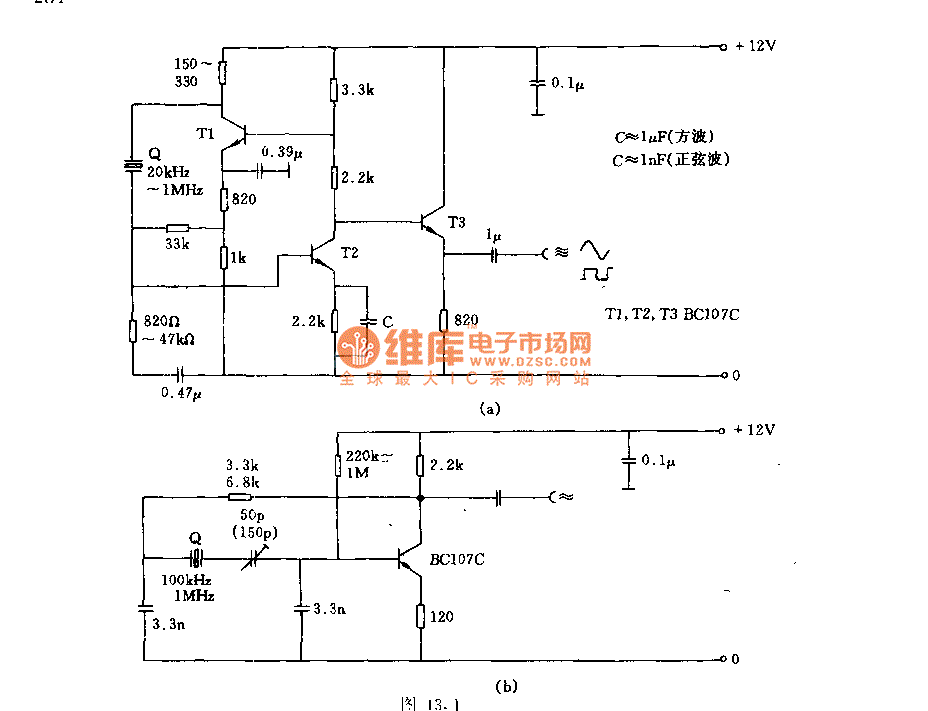
The crystal oscillator circuit with frequency in 2MHz
Figures (a) and (b) illustrate two basic oscillator circuits operating at 2 MHz. The circuit design allows for adjustment of the optimal operating point through testing.
The two oscillator circuits depicted in the figures utilize different configurations to achieve stable oscillation...
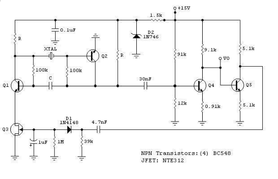
Low-Frequency Crystal Controlled Oscillator
The RF engineer often needs an instrument that can reliably and quickly check a low-frequency quartz crystal unit. However, such equipment is challenging to find, and engineers frequently refer to electronic circuit handbooks for schematics that can perform this task....
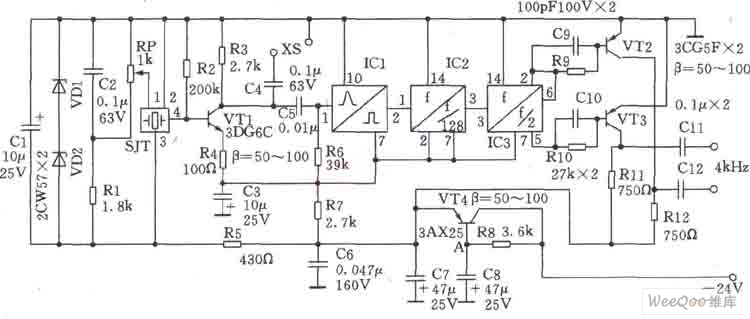
1024KHz temperature compensation crystal oscillator circuit diagram
This circuit is a 1024 kHz temperature-compensated crystal oscillator. The circuit theory is illustrated. Due to the low output signal level of the circuit, a buffer using the following transistor VT1 is implemented for amplification. The base bias resistor R2,...
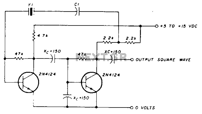
Frequency crystal oscillator circuit diagram of 10kHz-150kHz
A transistor in series with capacitor C1 can be utilized to adjust the oscillator output frequency. The frequency may vary with changes in capacitance ranging from 20 pF to 0.01 µF, or as determined by the tuning capacitor. The transistor...
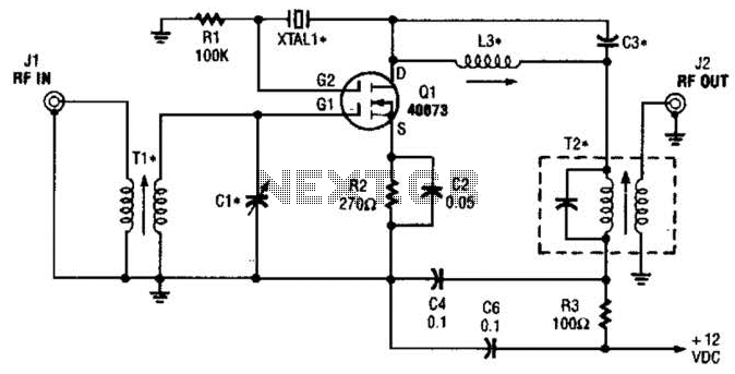
Crystal Controlled Frequency Converter Circuit
The second gate (G2) of a MOSFET can be utilized to integrate a crystal oscillator within the same stage as a frequency mixer. While this technique is common in tube technology, it is rarely implemented in dual-gate MOSFET circuits. Components...