


Oscillator Core Examples
#oscillator core
#Clapp oscillator
#Hartley oscillator
#Colpitts oscillator
#low resistance load
#50ohm load
#simulation
#measurement setup
#generic oscillator
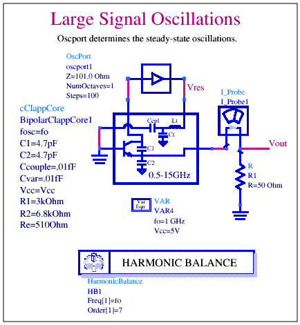
Description: Oscillator cores (cClappCore, cHartleyCore, cModifiedClappCore, and cModifiedColpittsCore) are compatible with simulation and measurement setups outlined by the Generic Oscillator Example. These core oscillator circuits are configured for low resistance loads (50 ohms is used for these four oscillator cores, although other load values are possible). The design and display filenames for these examples follow a naming convention that indicates oscillator type and simulation setup. SimulationType provides one of the following simulation setups or measurements: FixedFreqOsc, FreqPull, FreqPush, FreqTune, LSSpar, MapInput, MapOutput, NyqStab, or Phase Noise. For example, the simulation that determines oscillator frequency for a Clapp oscillator has the design filename ClappFixedFreqOsc.dsn and a data display filename ClappFixedFreqOsc.dds. This simulation predicts oscillation frequency, output power, and calculates tank components Lt and Ct. The accompanying data display presents these results. The Clapp oscillator harmonic balance simulation ClappFixedFreqOsc.dsn determines oscillation frequency, output power, and tank component values at 1 GHz. The OscPort probe is shown connected between the active device and tank resonator. Resonator tank components Lt and Ct are computed and shown on the companion data display page. One possibility connects the series resonator between the tank circuit and active device. If resonator losses are low, the series resonator can also be connected between the bipolar base terminal and ground. Several simulation setups connect portions of the tank circuit to ground reference. Performing the simulation issues warnings indicating some components are short-circuited, which are expected and should cause no concern. A load pull of the Clapp oscillator circuit shows that components Lt, Ct, and Ccpl are connected to ground and are not part of the actual simulation in this example. Short-circuited component warnings are issued for LSSpar, MapInput, and MapOutput simulations. The design and display filenames for these examples follow the generic oscillator naming convention with three-letter prefixes attached to the generic names. These oscillators are notable for their high frequency stability and low cost. The typical structure is that of a Colpitts oscillator with a quartz crystal resonator introduced into the feedback path. Mechanical vibrations of the crystal stabilize the oscillation frequency, which is sensitive to temperature. Therefore, temperature compensation circuits are often used to improve frequency stability. Crystal resonators are typically used in the range up to 100 MHz (and a few hundreds of MHz if resonating on overtones). The principle of operation is similar to that of a crystal oscillator, with the quartz resonator replaced by a Surface Acoustic Wave (SAW) oscillator. SAW resonators are used in frequency ranges up to 2 GHz. In any of the preceding structures, frequency tuning can be provided by adding a varactor diode to the resonator. The varactor diode serves as a voltage-controlled capacitor, offering very fast tuning speed (GHz/nsec) and low Q. Consequently, the varactor can be used with LC elements to provide wide tuning (with poor frequency stability) or with a crystal, SAW, or DRO resonator for narrow tuning with better frequency stability. At microwave frequencies, the device capacitances become significant, resulting in a different (often simpler) circuit. The operational principles remain the same. For very wide-band tuning, which can reach a decade, with high frequency stability and in the frequency range of 1 GHz to 50 GHz, YIG (Yttrium-Iron-Garnet) resonators are used. The YIG sphere behaves like a resonator with an unloaded Q of 1000 to 8000, resulting in very good frequency stability. The resonators are tunable over a wide bandwidth with excellent linearity (~0.05%). For fine tuning (for phase-lock) or frequency modulation, an FM coil can be added.
The oscillator cores described are designed for high performance in various applications, particularly in RF and microwave communications. The cClappCore, cHartleyCore, cModifiedClappCore, and cModifiedColpittsCore circuits are integral to understanding oscillator behavior under different loading conditions. The standard low resistance load of 50 ohms is optimal for these designs, ensuring compatibility with most measurement equipment and signal processing stages.
The simulation setups outlined provide a robust framework for analyzing oscillator performance. Each filename adheres to a systematic naming convention, which aids in identifying the specific simulation type and oscillator configuration. This structured approach facilitates easier navigation through simulation results and data displays.
In-depth analysis of the Clapp oscillator, as exemplified by the simulations, highlights the importance of tank circuit components, namely Lt and Ct, which critically influence the oscillator's output characteristics. The inclusion of the OscPort probe in the simulation allows for real-time monitoring of the oscillator's performance, ensuring that parameters such as output power and frequency can be accurately assessed.
The mention of temperature compensation circuits underscores the challenges faced in maintaining frequency stability, particularly in environments with variable temperatures. The use of crystal resonators and SAW oscillators reflects a trend toward higher frequency applications, with their inherent advantages in terms of stability and tuning capability.
Incorporating varactor diodes into the design allows for dynamic frequency adjustments, which is essential in applications requiring fine tuning and modulation. The characteristics of YIG resonators further enhance the versatility of these oscillator designs, providing options for high-frequency applications where traditional resonators may fall short.
Overall, the oscillator cores and their associated simulation setups represent a sophisticated approach to oscillator design, characterized by a blend of stability, performance, and adaptability to various operational conditions.Oscillator Cores (cClappCore, cHartleyCore, cModifiedClappCore, and cModifiedColpittsCore) are compatible with simulation and measurement setups outlined by the Generic Oscillator Example. These core oscillator circuits are configured for low resistance loads. (50ohm is used for these four oscillator cores, although other load values are possible. ) The design and display filenames for these examples follow a naming convention that indicates oscillator type and simulation setup as follows: SimulationType provides one of the following simulation set-ups or measurements: FixedFreqOsc, FreqPull, FreqPush, FreqTune, LSSpar, MapInput, MapOutput, NyqStab, or Phase Noise. For example, the simulation that determines oscillator frequency of a Clapp oscillator has the design filename ClappFixedFreqOsc.
dsn and a data display filename ClappFixedFreqOsc. dds. This simulation predicts oscillation frequency, output power, and calculates tank components Lt and Ct. The accompanying data display presents these results. Figure 2-23 shows the Clapp oscillator harmonic balance simulation ClappFixedFreqOsc. dsn that determines oscillation frequency, output power and tank component values at 1GHz. The OscPort probe is shown connected between the active device and tank resonator. Resonator tank components Lt and Ct are computed and shown on the companion data display page. The first possibility shown by Figure 2-24 connects the series resonator between the tank circuit and active device.
If resonator losses are low, the series resonator can also be connected between the bipolar base terminal and ground as shown in Figure 2-25. Several simulation setups connect portions of the tank circuit to ground reference. Performing the simulation issues warnings that indicate some components are short-circuited. These warnings are expected and should cause no concern. Figure 2-26 shows a load pull of the Clapp oscillator circuit. Notice that components Lt, Ct, and Ccpl are connected to ground and are not part of the actual simulation in this example.
Short-circuited component warnings are issued for LSSpar, MapInput, and MapOutput simulations. The design and display filenames for these examples follow the generic oscillator naming convention with 3-letter prefixes attached to the generic names, as follows: These oscillators are notable for their high frequency stability and low cost. Typical structure is that of a Colpitts oscillator with quartz crystal resonator introduced into feedback path.
Mechanical vibrations of the crystal stabilize the oscillations frequency. Vibration frequency is sensitive to temperature. Therefore, temperature compensation circuits are often used to improve frequency stability. Crystal resonators are typically used in the range up to 100 MHz (to a few hundreds of MHz if resonating on overtones). Principle of operation is similar to that of crystal oscillator with the quartz resonator replaced by a Surface Acoustic Wave oscillator.
SAW resonators are used in frequency range up to 2 GHz. In any of the preceding structures, frequency tuning can be provided by adding a varactor diode to the resonator. The varactor diode serves as a voltage controlled capacitor. It has very fast tuning speed (GHz/nsec) and low Q. Consequently, the varactor can be used with LC elements to provide wide tuning (with poor frequency stability) or with a crystal, SAW or DRO resonator for narrow tuning with better frequency stability.
At microwave frequencies, the device capacitances become significant, resulting in a different (often simpler) circuit. The operation principles, remain the same. For a very wide band (that can reach decade) tuning with high frequency stability and for frequency range of 1 GHz to 50 GHz.
YIG (Yttrium-Iron-Garnett) resonators are used. The YIG sphere behaves like a resonator with 1000-to-8000 unloaded Q resulting in very good frequency stability. The resonator are tunable over wide bandwidth with excellent linearity (~0. 05%). For fine tuning (for phase-lock), or frequency modulation an FM coil can be added.
The oscillator cores described are designed for high performance in various applications, particularly in RF and microwave communications. The cClappCore, cHartleyCore, cModifiedClappCore, and cModifiedColpittsCore circuits are integral to understanding oscillator behavior under different loading conditions. The standard low resistance load of 50 ohms is optimal for these designs, ensuring compatibility with most measurement equipment and signal processing stages.
The simulation setups outlined provide a robust framework for analyzing oscillator performance. Each filename adheres to a systematic naming convention, which aids in identifying the specific simulation type and oscillator configuration. This structured approach facilitates easier navigation through simulation results and data displays.
In-depth analysis of the Clapp oscillator, as exemplified by the simulations, highlights the importance of tank circuit components, namely Lt and Ct, which critically influence the oscillator's output characteristics. The inclusion of the OscPort probe in the simulation allows for real-time monitoring of the oscillator's performance, ensuring that parameters such as output power and frequency can be accurately assessed.
The mention of temperature compensation circuits underscores the challenges faced in maintaining frequency stability, particularly in environments with variable temperatures. The use of crystal resonators and SAW oscillators reflects a trend toward higher frequency applications, with their inherent advantages in terms of stability and tuning capability.
Incorporating varactor diodes into the design allows for dynamic frequency adjustments, which is essential in applications requiring fine tuning and modulation. The characteristics of YIG resonators further enhance the versatility of these oscillator designs, providing options for high-frequency applications where traditional resonators may fall short.
Overall, the oscillator cores and their associated simulation setups represent a sophisticated approach to oscillator design, characterized by a blend of stability, performance, and adaptability to various operational conditions.Oscillator Cores (cClappCore, cHartleyCore, cModifiedClappCore, and cModifiedColpittsCore) are compatible with simulation and measurement setups outlined by the Generic Oscillator Example. These core oscillator circuits are configured for low resistance loads. (50ohm is used for these four oscillator cores, although other load values are possible. ) The design and display filenames for these examples follow a naming convention that indicates oscillator type and simulation setup as follows: SimulationType provides one of the following simulation set-ups or measurements: FixedFreqOsc, FreqPull, FreqPush, FreqTune, LSSpar, MapInput, MapOutput, NyqStab, or Phase Noise. For example, the simulation that determines oscillator frequency of a Clapp oscillator has the design filename ClappFixedFreqOsc.
dsn and a data display filename ClappFixedFreqOsc. dds. This simulation predicts oscillation frequency, output power, and calculates tank components Lt and Ct. The accompanying data display presents these results. Figure 2-23 shows the Clapp oscillator harmonic balance simulation ClappFixedFreqOsc. dsn that determines oscillation frequency, output power and tank component values at 1GHz. The OscPort probe is shown connected between the active device and tank resonator. Resonator tank components Lt and Ct are computed and shown on the companion data display page. The first possibility shown by Figure 2-24 connects the series resonator between the tank circuit and active device.
If resonator losses are low, the series resonator can also be connected between the bipolar base terminal and ground as shown in Figure 2-25. Several simulation setups connect portions of the tank circuit to ground reference. Performing the simulation issues warnings that indicate some components are short-circuited. These warnings are expected and should cause no concern. Figure 2-26 shows a load pull of the Clapp oscillator circuit. Notice that components Lt, Ct, and Ccpl are connected to ground and are not part of the actual simulation in this example.
Short-circuited component warnings are issued for LSSpar, MapInput, and MapOutput simulations. The design and display filenames for these examples follow the generic oscillator naming convention with 3-letter prefixes attached to the generic names, as follows: These oscillators are notable for their high frequency stability and low cost. Typical structure is that of a Colpitts oscillator with quartz crystal resonator introduced into feedback path.
Mechanical vibrations of the crystal stabilize the oscillations frequency. Vibration frequency is sensitive to temperature. Therefore, temperature compensation circuits are often used to improve frequency stability. Crystal resonators are typically used in the range up to 100 MHz (to a few hundreds of MHz if resonating on overtones). Principle of operation is similar to that of crystal oscillator with the quartz resonator replaced by a Surface Acoustic Wave oscillator.
SAW resonators are used in frequency range up to 2 GHz. In any of the preceding structures, frequency tuning can be provided by adding a varactor diode to the resonator. The varactor diode serves as a voltage controlled capacitor. It has very fast tuning speed (GHz/nsec) and low Q. Consequently, the varactor can be used with LC elements to provide wide tuning (with poor frequency stability) or with a crystal, SAW or DRO resonator for narrow tuning with better frequency stability.
At microwave frequencies, the device capacitances become significant, resulting in a different (often simpler) circuit. The operation principles, remain the same. For a very wide band (that can reach decade) tuning with high frequency stability and for frequency range of 1 GHz to 50 GHz.
YIG (Yttrium-Iron-Garnett) resonators are used. The YIG sphere behaves like a resonator with 1000-to-8000 unloaded Q resulting in very good frequency stability. The resonator are tunable over wide bandwidth with excellent linearity (~0. 05%). For fine tuning (for phase-lock), or frequency modulation an FM coil can be added.
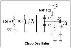
Hartley
A Hartley oscillator is shown at the right. It uses most of the same components as the Clapp oscillator. A capacitor is necessary to block the gate bias voltage from the tuned circuit. The tuning capacitor is a 100 pF...
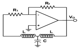
HARTLEY OSCILLATOR
The Hartley oscillator is an LC electronic oscillator that derives its feedback from a tapped coil in parallel with a capacitor, forming the tank circuit. While mutual coupling between the two coil segments is not a requirement, the circuit is...
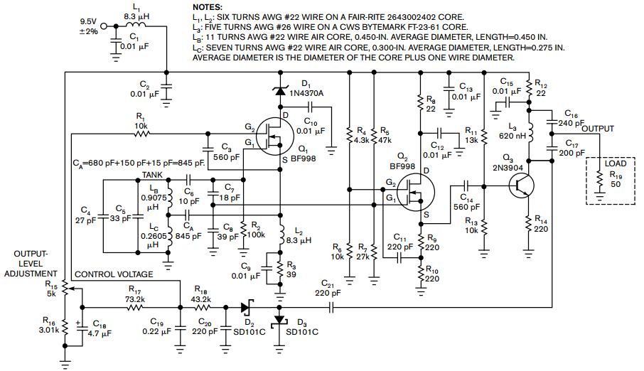
Hartley oscillator requires no coupled inductors
Examine a traditional Hartley oscillator circuit, and you'll note its trademark: a tapped inductor that determines the frequency of oscillation and provides oscillation-sustaining feedback. Although you can easily calculate the total inductance required for a given frequency, finding the coupling...
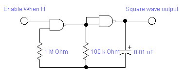
oscillator
The Colpitts oscillator circuit schematic is closely related to the shunt-fed Hartley oscillator, with the primary distinction being in the tank circuit design. In the Colpitts oscillator, two capacitors are utilized in place of divided coils. The basic feedback oscillator...
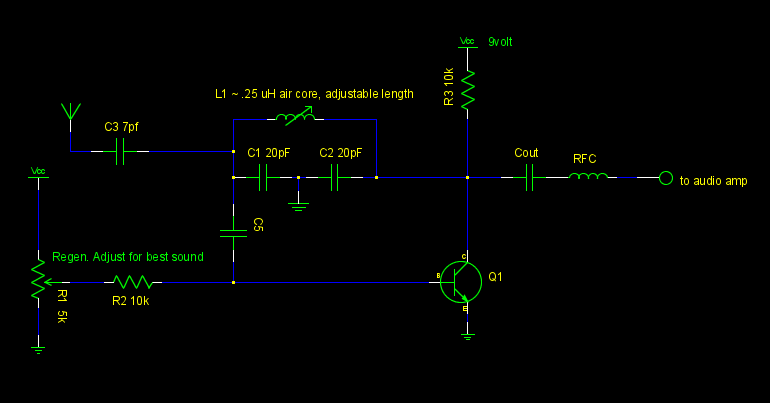
controlling feedback on colpitts oscillator(VHF/FM)
A common emitter Colpitts oscillator was constructed using variable capacitors for C1 and C2, and a few turns of wire wrapped around a pencil for the inductor L. Resistors R1 and R2 were replaced with a trimmer potentiometer to allow...
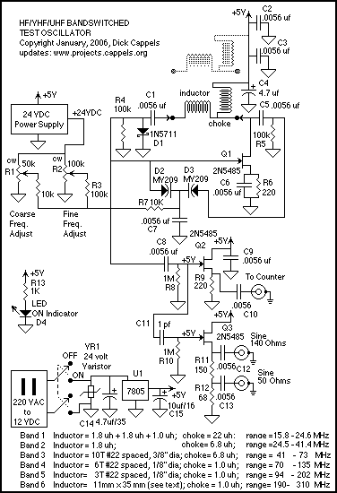
16-300 MHz Testing Colpitts oscillator
The circuit is a modified Colpitts oscillator, tuned with MV209 varactor diodes. The resonating inductor and the drain choke are selected by a rotary switch. 1N5711 Schottky diode, D, clamps the maximum positive voltage on the gate of oscillator FET,...
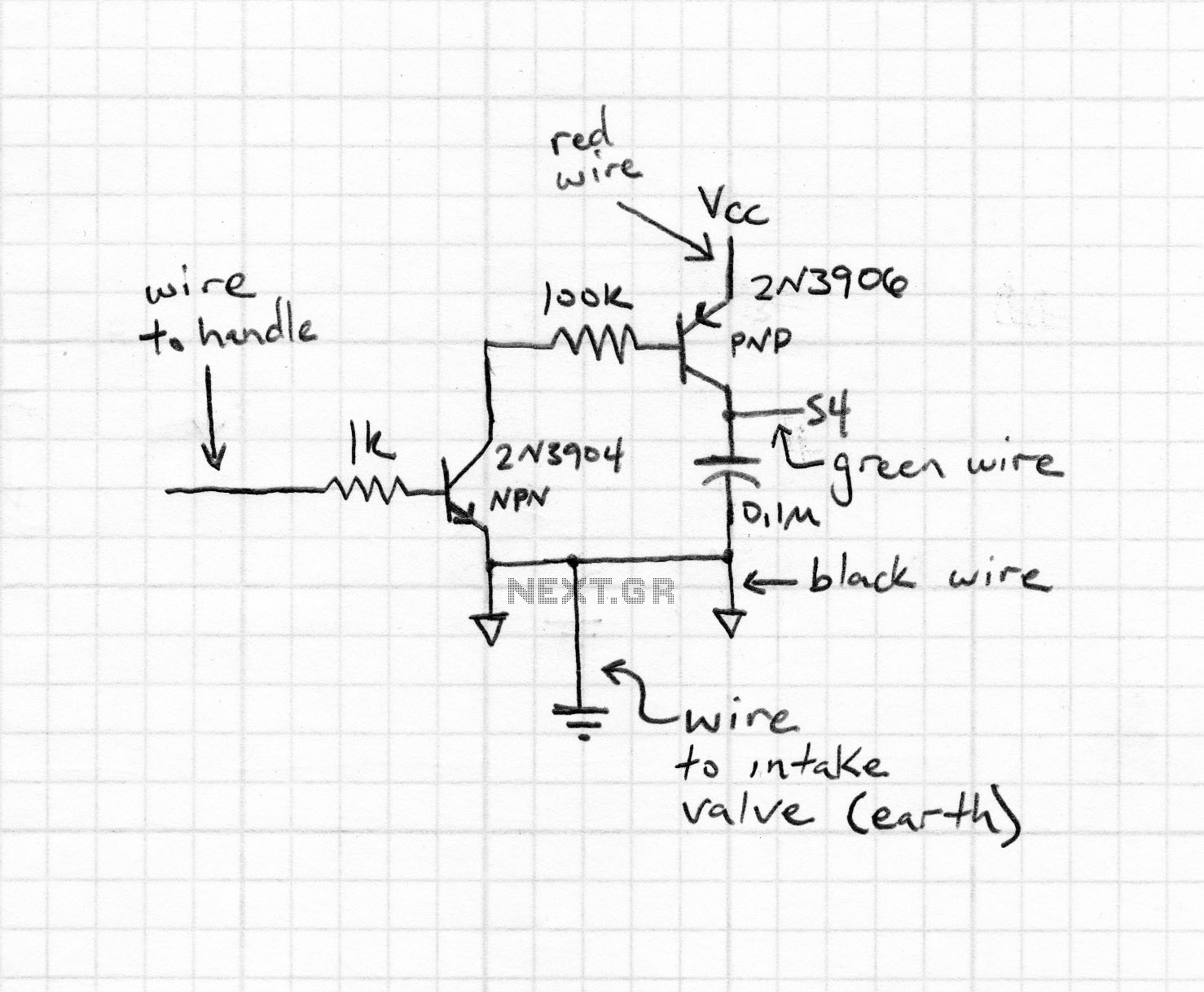
local oscillator
Zener diodes were utilized to derive a stabilized voltage for the Hartley oscillator. While sorting through a box of valves, suitable voltage stabilizer valves (CV287) were discovered. During this process, the ECC81 utilized in the local oscillator was noted to...
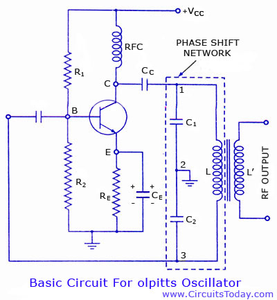
Colpitts oscillator using transistor. Circuit diagram and theory
Colpitts oscillator circuit diagram and theory. Colpitts oscillator frequency equation. Colpitts oscillator using transistor. Colpitts oscillator using op-amp.
The Colpitts oscillator is a type of electronic oscillator that generates sine waves and is widely used in various applications such as radio...
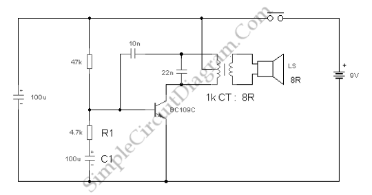
Electronic Canary
This circuit is a modification of the Hartley oscillator, incorporating several additional components. It utilizes a small audio transformer.
The modified Hartley oscillator circuit enhances the traditional design by integrating extra components that can improve performance characteristics such as stability, frequency...