


Pierce harmonic oscillator 20Mhz
#Pierce oscillator
#harmonic oscillator
#20MHz
#crystal oscillator
#frequency stability
#capacitive load
#resonant circuit
#high frequency
#electronic oscillator
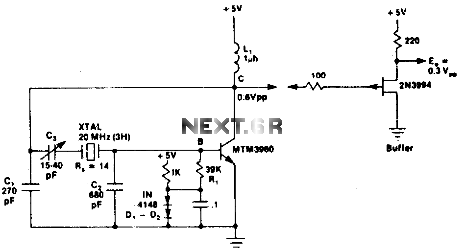
Description: This circuit exhibits excellent short-term frequency stability due to the external load connected across the crystal, which is predominantly capacitive rather than resistive. This configuration results in a high in-circuit quality factor (Q) for the crystal.
The circuit utilizes a crystal oscillator configuration that leverages the properties of the crystal to achieve superior frequency stability. The crystal is connected in a manner that minimizes resistive loading, allowing it to operate closer to its natural resonant frequency. The predominant capacitive load enhances the crystal's Q factor, which is a measure of its energy loss relative to the energy stored in the system.
In practical terms, a high Q factor indicates that the crystal can maintain its oscillation frequency with minimal drift over short periods, making it ideal for applications that require precise timing signals. The capacitive loading can be achieved through the use of capacitors that are strategically placed in parallel with the crystal. This arrangement allows for fine-tuning of the oscillator's frequency and improves its overall stability.
Furthermore, the circuit may include additional components such as feedback resistors and operational amplifiers to further enhance performance and ensure that the oscillator maintains a consistent output. The design should also consider temperature compensation techniques to mitigate frequency variations caused by changes in ambient temperature, thereby preserving the integrity of the oscillation frequency.
Overall, this circuit design is well-suited for applications in communication systems, clock generation, and other electronic devices where frequency precision is critical.This circuit has excellent short term frequency stability because the external load tied across the crystal is mostly capacitive rather than resistive giving the crystal a high in-circuit Q.
The circuit utilizes a crystal oscillator configuration that leverages the properties of the crystal to achieve superior frequency stability. The crystal is connected in a manner that minimizes resistive loading, allowing it to operate closer to its natural resonant frequency. The predominant capacitive load enhances the crystal's Q factor, which is a measure of its energy loss relative to the energy stored in the system.
In practical terms, a high Q factor indicates that the crystal can maintain its oscillation frequency with minimal drift over short periods, making it ideal for applications that require precise timing signals. The capacitive loading can be achieved through the use of capacitors that are strategically placed in parallel with the crystal. This arrangement allows for fine-tuning of the oscillator's frequency and improves its overall stability.
Furthermore, the circuit may include additional components such as feedback resistors and operational amplifiers to further enhance performance and ensure that the oscillator maintains a consistent output. The design should also consider temperature compensation techniques to mitigate frequency variations caused by changes in ambient temperature, thereby preserving the integrity of the oscillation frequency.
Overall, this circuit design is well-suited for applications in communication systems, clock generation, and other electronic devices where frequency precision is critical.This circuit has excellent short term frequency stability because the external load tied across the crystal is mostly capacitive rather than resistive giving the crystal a high in-circuit Q.
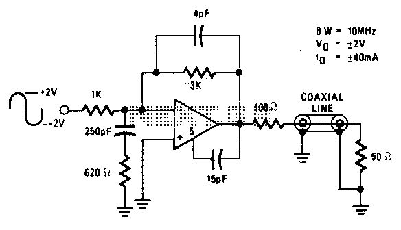
10Mhz coaxial line driver
The circuit is ideal for high-frequency line driving systems that necessitate a wide power bandwidth at elevated output current levels. The integrated circuit used is HA2530. The bandwidth of the circuit is constrained solely by the single pole response of...
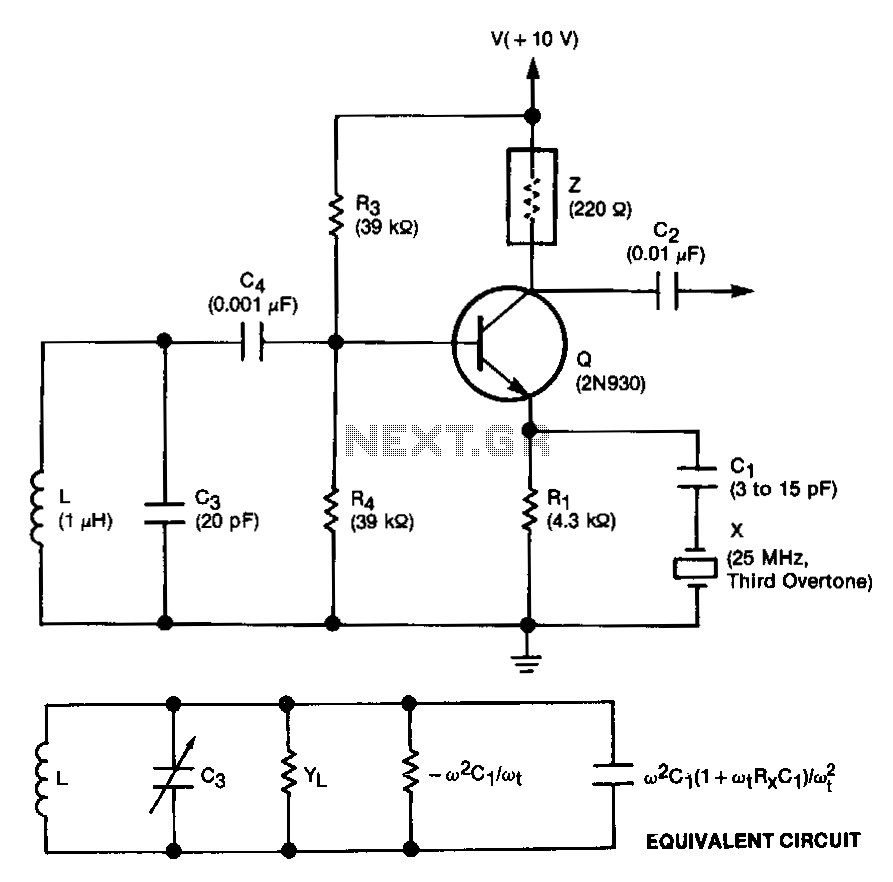
Crystal-controlled-reflection-oscillator
This unit is easily tunable and stable, consumes minimal power, and is more cost-effective than other types of oscillators that operate at similar frequencies. This unique combination of features is made possible by a design concept that involves operating the...
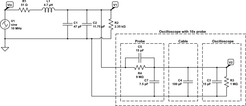
Crystal oscillator simulation
The initial intention for this posting was to title it "Crystal Oscillator Blues," reflecting the challenges faced in constructing the crystal oscillator for the GPS Disciplined Oscillator (GPSDO), as mentioned in a previous post. However, there have been some positive...
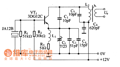
27MHz crystal oscillator circuit
The 27MHz crystal oscillator circuit is illustrated in the figure. Resistors R1, R2, and R3 serve as biasing resistors, while capacitor C6 functions as a bypass capacitor. The voltage division circuit consists of capacitors C1, C3, C4, and C2, which...
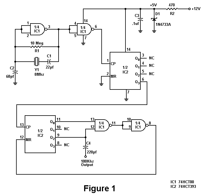
100KHz Crystal Oscillator
There is a significant amount of vintage amateur equipment that many enthusiasts have chosen to restore and rejuvenate. Although many early amateur transceivers operate effectively, they typically lack a digital readout and depend on analog dials for tuning. The challenge...
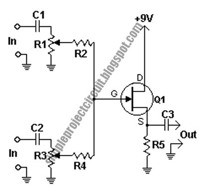
pierce xtal oscillator circuit
This circuit is a conventional Pierce type oscillator that utilizes a JFET. It operates with fundamental mode crystals and exhibits good performance and reliability when a low noise JFET is employed. The feedback is regulated by the capacitance of C1...
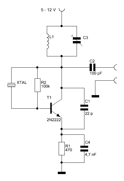
overtone crystal oscillator
Crystals with higher frequencies than approximately 30 MHz are predominantly overtone crystals. These crystals are designed to operate at an odd multiple of their fundamental frequency. However, they do not resonate at their overtone frequency without assistance; the oscillator circuit...
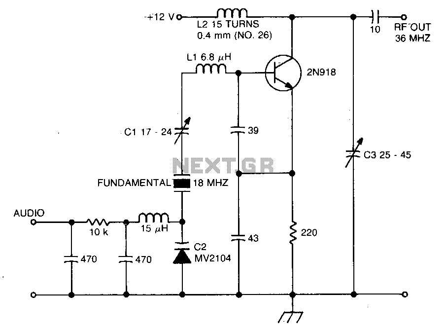
Crystal oscillator-doubler
The crystal operates into a complex load at series resonance. L1, C1, and C2 balance the crystal at zero reactance. Capacitor C1 fine-tunes the center frequency. A tank circuit consisting of L2 and C3 doubles the output frequency, allowing the...
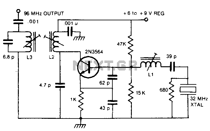
96Mhz crystal oscillator
By utilizing a crystal oscillator operating between 27 and 33 MHz, the third harmonic frequency will produce an output ranging from 82 to 99 MHz.
The implementation of a crystal oscillator within the specified frequency range of 27 to 33 MHz...