


RC Oscillator Oscillator Tutorial
#RC oscillator
#phase shift
#sine wave
#tuned circuit
#electronics tutorial
#frequency generation
#RC network
#feedback circuit
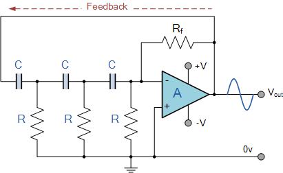
Description: Electronics tutorial about the RC oscillator circuit, RC phase shift oscillators, and how a tuned RC oscillator circuit produces sine waves.
The RC oscillator circuit is a fundamental electronic circuit used to generate oscillating signals, particularly sine waves. This circuit typically employs resistors (R) and capacitors (C) to create a feedback loop that enables continuous oscillation. The RC phase shift oscillator is a specific type of RC oscillator that utilizes a network of resistors and capacitors to produce a phase shift of 180 degrees, which is essential for sustaining oscillations.
In the basic configuration of an RC phase shift oscillator, three or more RC stages are used to achieve the required phase shift. Each RC stage contributes 60 degrees of phase shift, amounting to a total of 180 degrees when combined with the 180-degree phase shift provided by an inverting amplifier, such as a transistor or an operational amplifier. The output frequency of the oscillator can be determined by the values of the resistors and capacitors used in the circuit.
The tuned RC oscillator circuit, on the other hand, is designed to produce sine waves with a specific frequency. This is achieved by tuning the circuit to resonate at a desired frequency, often using an inductor along with the RC components. The resonance condition enhances the amplitude of the output sine wave, making it suitable for applications that require stable and pure sine wave signals.
In summary, RC oscillators, particularly the phase shift and tuned types, are critical components in various electronic applications, including waveform generation, signal modulation, and clock generation in digital circuits. Understanding the principles behind these oscillators is essential for designing effective electronic systems that require precise frequency control and signal integrity.Electronics Tutorial about the RC Oscillator Circuit, RC Phase Shift Oscillators and how a Tuned RC Oscillator Circuit produces sine waves..
The RC oscillator circuit is a fundamental electronic circuit used to generate oscillating signals, particularly sine waves. This circuit typically employs resistors (R) and capacitors (C) to create a feedback loop that enables continuous oscillation. The RC phase shift oscillator is a specific type of RC oscillator that utilizes a network of resistors and capacitors to produce a phase shift of 180 degrees, which is essential for sustaining oscillations.
In the basic configuration of an RC phase shift oscillator, three or more RC stages are used to achieve the required phase shift. Each RC stage contributes 60 degrees of phase shift, amounting to a total of 180 degrees when combined with the 180-degree phase shift provided by an inverting amplifier, such as a transistor or an operational amplifier. The output frequency of the oscillator can be determined by the values of the resistors and capacitors used in the circuit.
The tuned RC oscillator circuit, on the other hand, is designed to produce sine waves with a specific frequency. This is achieved by tuning the circuit to resonate at a desired frequency, often using an inductor along with the RC components. The resonance condition enhances the amplitude of the output sine wave, making it suitable for applications that require stable and pure sine wave signals.
In summary, RC oscillators, particularly the phase shift and tuned types, are critical components in various electronic applications, including waveform generation, signal modulation, and clock generation in digital circuits. Understanding the principles behind these oscillators is essential for designing effective electronic systems that require precise frequency control and signal integrity.Electronics Tutorial about the RC Oscillator Circuit, RC Phase Shift Oscillators and how a Tuned RC Oscillator Circuit produces sine waves..
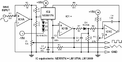
sine to square triangle wave
If a triangle wave signal or a square wave is required but only a sine wave generator is available, this converter can be utilized to simplify the process. The circuit consists of two integrated circuits (ICs): an LM13700 and a...

Sine Wave To TTL Converter
The circuit is designed to convert sinusoidal input signals into TTL output signals and can process input voltages exceeding 100 mV.
This circuit typically employs a comparator to achieve the conversion from sinusoidal to TTL levels. The sinusoidal input signal is...
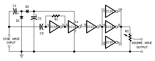
Self-powered Sine to Square wave Converters
This circuit is designed to produce square waves by converting a sine wave obtained from an existing generator. A key feature is that it requires no external power source, allowing for simple connection between a sine wave generator and the...
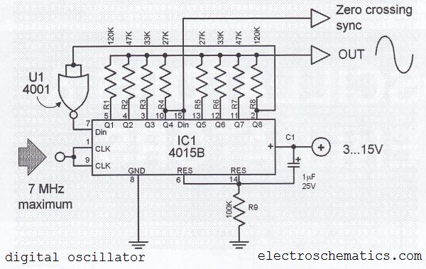
Digital Sine Wave Generator Circuit
The digital sine wave generator (oscillator) circuit requires only a few components to produce signals with high amplitude constants and a wide range of variable frequencies. This circuit generates a sine wave signal, and by altering the values of resistors...
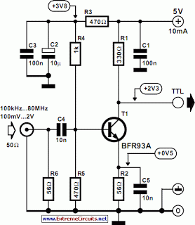
sine wave to ttl converter
The current circuit is designed to convert sinusoidal input signals into TTL output signals. It is capable of handling input signals greater than 100 mV and operates effectively at frequencies up to approximately 80 MHz. Transistor T1 is configured in...
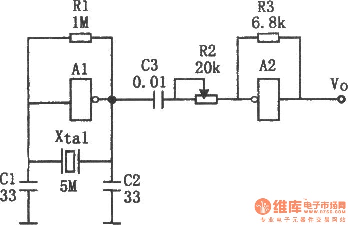
Sine wave generator composed of inverter
The sine wave generator composed of an inverter is illustrated in the chart. This circuit can produce a high-stability sine wave at frequencies exceeding a few megahertz. In the diagram, A1 and the crystal oscillator create an oscillating circuit, with...
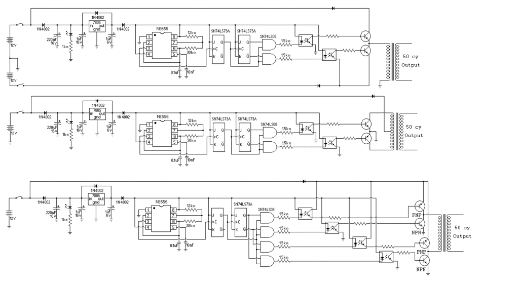
Modified Sine Wave Signal Generator
A comprehensive understanding is required to design an inverter effectively. The design of the circuit is largely influenced by the availability of a custom-made transformer.
To design an inverter, various factors must be considered, including the input and output voltage requirements,...
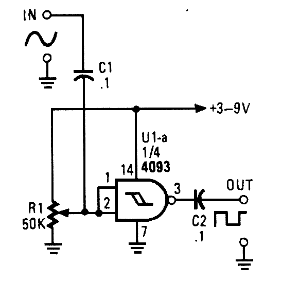
SINE WAVE TO SQUARE WAVE CONVERTER
This circuit converts a sine wave into a square wave. It consists of a single 2-input NAND Schmitt trigger configured as an inverter, with a trigger level adjustment at its input. As the input voltage exceeds the gate's trigger point,...
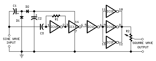
self powered sine to square wave converter
This circuit is designed to generate high-quality square waves by converting a sine wave obtained from an existing generator. A key feature of this circuit is that it does not require an external power source; it can be directly connected...