


Sawtooth voltage controlled oscillator
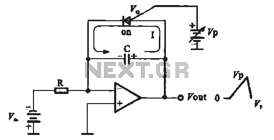
Description: A sawtooth voltage-controlled oscillator operates by first generating a negative potential maximum at the output of the comparator. This output is then fed to the inverting input terminal through resistor R1, which is part of the relaxation oscillator. The relaxation oscillator produces a positive phase voltage ramp. When this ramp voltage reaches a trigger point, the input to the comparator also achieves a positive potential maximum. This positive potential causes the ramp voltage of the relaxation oscillator to gradually decrease from its peak and move towards negative voltage. The ramp voltage continues to decline until it reaches the next trigger point of the comparator. At this stage, the comparator input drops to a negative potential maximum, and the cycle repeats, resulting in a continuous triangular wave output. When the input to the relaxation oscillator is controlled by an adjustable DC voltage, the triangular wave output becomes a sawtooth waveform. The voltage control signal can be a sine wave. If the input signal terminal is connected to a controlled thyristor (PUT) with a feedback capacitor in parallel, each ramp voltage slope can be cut off at a specified level. Initially, the sawtooth oscillator generates a positive phase ramp from a negative DC input voltage (-Vin). When the gate voltage of the thyristor exceeds the output ramp voltage of 0.7 V, the single-junction thyristor is triggered into conduction. The gate voltage is set approximately equal to the expected peak of the sawtooth voltage. When the PUT conducts, the capacitor discharges rapidly. Due to the positive phase relationship between voltage (VF) and the PUT, the capacitor does not fully discharge to zero. The discharge process continues until the current falls below the holding current, at which point the single-junction thyristor turns off, and the capacitor begins to charge again, creating a new output voltage ramp. This cycle repeats, producing a sawtooth waveform output, with the amplitude and period of the sawtooth wave adjustable via the PUT gate voltage.
A sawtooth voltage-controlled oscillator (VCO) is a crucial component in various electronic applications, particularly in signal generation and waveform shaping. The operation begins with a comparator that outputs a negative voltage, which is then routed to the inverting input of the circuit through resistor R1. This configuration is integral to the relaxation oscillator's function, which generates a positive voltage ramp. The ramp voltage's ascent continues until it reaches a predetermined threshold, known as the trigger point. At this juncture, the comparator's input also reaches a positive potential maximum, prompting the relaxation oscillator to initiate a downward slope in the ramp voltage.
As the ramp voltage descends toward the next trigger point, the comparator input transitions to a negative potential maximum, thereby creating a cyclical output characteristic of triangular waveforms. This triangular output can be transformed into a sawtooth waveform by introducing a variable DC voltage to the relaxation oscillator's input. The adaptability of the input voltage allows for versatile control over the output waveform's characteristics.
The inclusion of a controlled thyristor (PUT) in conjunction with a feedback capacitor further enhances the oscillator's functionality. This setup allows for precise control over the ramp voltage's discharge level. When the thyristor's gate voltage surpasses the ramp voltage threshold of 0.7 V, it triggers conduction, resulting in a rapid discharge of the capacitor. However, due to the inherent properties of the PUT, the capacitor does not fully discharge, which is essential for maintaining the oscillation cycle.
The discharge process persists until the current through the thyristor drops below its holding current, at which point the thyristor turns off, allowing the capacitor to recharge and initiate a new ramp voltage cycle. This repetitive process generates a sawtooth waveform, where the amplitude and period can be finely tuned by adjusting the gate voltage of the PUT. The sawtooth voltage-controlled oscillator thus serves as a critical element in applications requiring precise waveform generation and control, such as in timing circuits, signal modulation, and waveform synthesis.B sawtooth voltage controlled oscillator First, the output voltage of the comparator is a negative potential maximum. Then the output to the inverting input terminal R1 via the relaxation oscillator at the output of the relaxation oscillator to generate a positive phase voltage ramp. When the ramp voltage reaches the trigger point, input of the comparator has also been positive potential maximum.
This positive potential so that the relaxation oscillator ramp voltage gradually decreased from the highest point, and changes to the negative voltage direction. Ramp voltage in this direction continued to decline until the comparator until the next trigger point.
Then the comparator input also dropped to a negative potential maximum, and continue to repeat this cycle, the output of the continuous triangular wave. When the input of the relaxation oscillator with adjustable DC voltage control, the triangular wave oscillator becomes a sawtooth oscillator.
Voltage control signal may be a sine wave or sine wave, if the input signal terminal with controlled thyristor PUT feedback capacitor in parallel, so that each ramp voltage slope off at a specified level, as shown in Figure 16-22. First, a sawtooth oscillator initially negative DC input voltage - Vin generating at the output a positive phase ramp.
When a male thyristor controlled single-junction electrode when the gate voltage exceeds the output ramp voltage 0.7 V, single-junction is triggered thyristor conduction. Set the value of the gate voltage roughly equal to the expected peak of the sawtooth voltage. When PUT conduction, discharge the capacitor quickly, as shown in Figure 16-22 (b). Because PUT positive phase relationship between voltage VF, the capacitor will not be fully discharged to zero.
PUT discharge process continues until the current below the holding current. At this single-junction off thyristor will, once again begins to charge the capacitor, thus creating new output voltage ramp. This cycle is repeated, the output signal would be a repeat of the sawtooth waveform, amplitude and period of the sawtooth wave may be changed by the PUT gate voltage must be adjusted.
A sawtooth voltage-controlled oscillator (VCO) is a crucial component in various electronic applications, particularly in signal generation and waveform shaping. The operation begins with a comparator that outputs a negative voltage, which is then routed to the inverting input of the circuit through resistor R1. This configuration is integral to the relaxation oscillator's function, which generates a positive voltage ramp. The ramp voltage's ascent continues until it reaches a predetermined threshold, known as the trigger point. At this juncture, the comparator's input also reaches a positive potential maximum, prompting the relaxation oscillator to initiate a downward slope in the ramp voltage.
As the ramp voltage descends toward the next trigger point, the comparator input transitions to a negative potential maximum, thereby creating a cyclical output characteristic of triangular waveforms. This triangular output can be transformed into a sawtooth waveform by introducing a variable DC voltage to the relaxation oscillator's input. The adaptability of the input voltage allows for versatile control over the output waveform's characteristics.
The inclusion of a controlled thyristor (PUT) in conjunction with a feedback capacitor further enhances the oscillator's functionality. This setup allows for precise control over the ramp voltage's discharge level. When the thyristor's gate voltage surpasses the ramp voltage threshold of 0.7 V, it triggers conduction, resulting in a rapid discharge of the capacitor. However, due to the inherent properties of the PUT, the capacitor does not fully discharge, which is essential for maintaining the oscillation cycle.
The discharge process persists until the current through the thyristor drops below its holding current, at which point the thyristor turns off, allowing the capacitor to recharge and initiate a new ramp voltage cycle. This repetitive process generates a sawtooth waveform, where the amplitude and period can be finely tuned by adjusting the gate voltage of the PUT. The sawtooth voltage-controlled oscillator thus serves as a critical element in applications requiring precise waveform generation and control, such as in timing circuits, signal modulation, and waveform synthesis.B sawtooth voltage controlled oscillator First, the output voltage of the comparator is a negative potential maximum. Then the output to the inverting input terminal R1 via the relaxation oscillator at the output of the relaxation oscillator to generate a positive phase voltage ramp. When the ramp voltage reaches the trigger point, input of the comparator has also been positive potential maximum.
This positive potential so that the relaxation oscillator ramp voltage gradually decreased from the highest point, and changes to the negative voltage direction. Ramp voltage in this direction continued to decline until the comparator until the next trigger point.
Then the comparator input also dropped to a negative potential maximum, and continue to repeat this cycle, the output of the continuous triangular wave. When the input of the relaxation oscillator with adjustable DC voltage control, the triangular wave oscillator becomes a sawtooth oscillator.
Voltage control signal may be a sine wave or sine wave, if the input signal terminal with controlled thyristor PUT feedback capacitor in parallel, so that each ramp voltage slope off at a specified level, as shown in Figure 16-22. First, a sawtooth oscillator initially negative DC input voltage - Vin generating at the output a positive phase ramp.
When a male thyristor controlled single-junction electrode when the gate voltage exceeds the output ramp voltage 0.7 V, single-junction is triggered thyristor conduction. Set the value of the gate voltage roughly equal to the expected peak of the sawtooth voltage. When PUT conduction, discharge the capacitor quickly, as shown in Figure 16-22 (b). Because PUT positive phase relationship between voltage VF, the capacitor will not be fully discharged to zero.
PUT discharge process continues until the current below the holding current. At this single-junction off thyristor will, once again begins to charge the capacitor, thus creating new output voltage ramp. This cycle is repeated, the output signal would be a repeat of the sawtooth waveform, amplitude and period of the sawtooth wave may be changed by the PUT gate voltage must be adjusted.
Simple voltage controlled oscillator
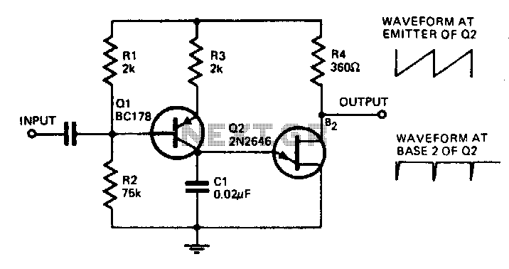
With the component values shown, the oscillator has a frequency of 8 kHz. When an input signal is applied to the base of Q1, the current flowing through Q1 is varied, thus affecting the time required to charge C1. Due...
simple analog comparator
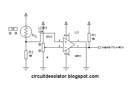
This is a common circuit block utilized in both digital and analog electronics. Its output depends on the relationship between its two input pins. One input is designated to provide the reference voltage, while the other is typically connected to...
Voltage Controlled Oscillator with BF990A
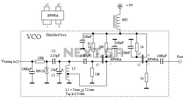
The VCO is based on a Hartley oscillator. The frequency is determined by L1 and capacitor C1. The tuning voltage will change the capacitance in the varactor BB132 which will change the oscillation frequency. The value of capacitor C2 will...
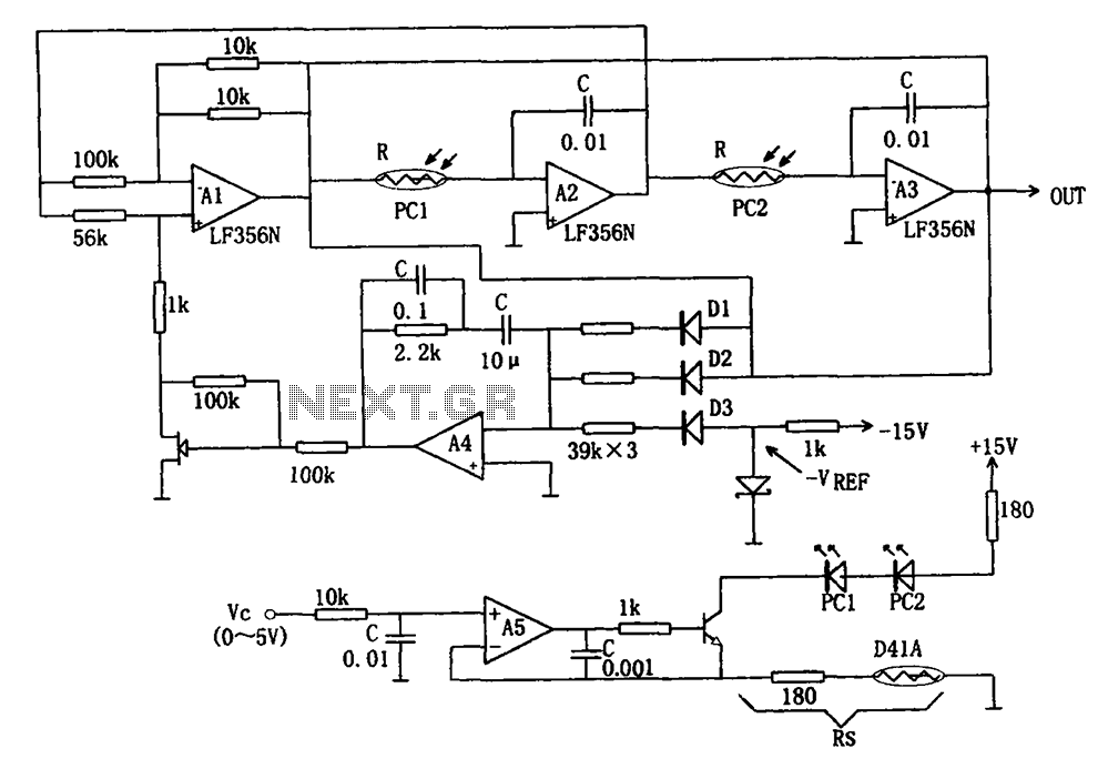
Broadband sine wave voltage controlled oscillator circuit diagram LF356N
The wideband sinusoidal voltage-controlled oscillator circuit is designed such that the oscillation frequency is determined by an integrating resistor R and a capacitor C. The voltage-controlled oscillator is constituted by the applied control voltage Vc and a control resistor R....
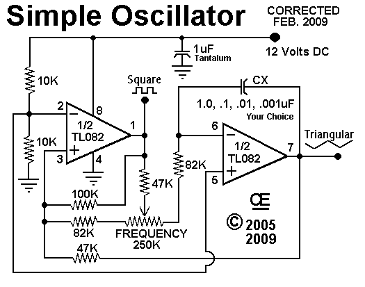
Sawtooth and Squarewave Oscillator
The control on the PCB is set at specific positions with the following capacitance values and their corresponding measured frequencies: For a capacitance of 100 pF, the frequencies are 6 kHz, 12.05 kHz, and 26 kHz. For 470 pF, the...
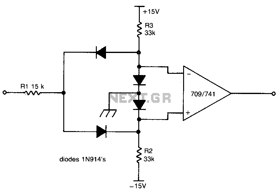
Dual limit comparator
This circuit provides a positive output when the input voltage exceeds 8 volts. Within these limits, the output remains negative. The threshold for the positive output is set by the ratio of resistors R1 and R2, while the threshold for...
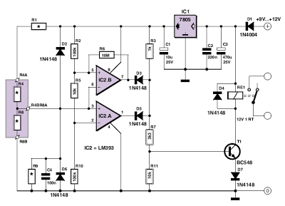
Simple Analogue Electronic Key
This circuit utilizes two comparators configured as a window comparator. Resistors R2, R5, and R10 establish a voltage window within which the voltage at the junction of D2 and D6 must reside for the outputs of IC2.A and IC2.B to...
IC Magnitude Comparators
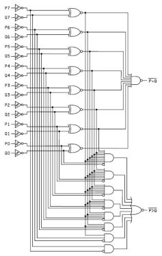
This Magnitude Comparator can be used to perform comparisons of two 8-bit binary or BCD words. The output provides both a P equals Q function and a P greater than Q function. A Magnitude Comparator is typically classified as standard...
Power-supply-balance-indicator
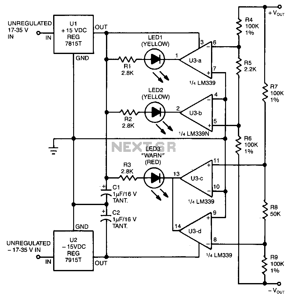
This circuit utilizes two pairs of comparators from an LM339N quad comparator. One pair controls the yellow positive (+) and negative (-) indicators, while the other pair drives the red warning LED3. The circuit is powered by the unregulated section...