


Simple Toy Organ using 555
#555 timer
#audio oscillator
#toy organ
#variable resistors
#frequency tuning
#simple oscillator
#electronic music
#sound generation
#educational circuits

Description: This is a simple oscillator with multiple resistors in series. When you press any switch, the circuit starts oscillating. You can use variable resistors instead of the 1k resistors. Using variable resistors, you will be able to tune the frequency for each note. You cannot press two keys at the same time because the frequency will change. To make an electronic organ capable of pressing many keys at the same time, you may need to use thirteen 555 ICs. It is okay to use 9 to 12V as power, but it may be quite loud. It is not recommended to use a power supply as it may cause electrical shock. Also, a "hum" will be audible while it is in use.
The described circuit functions as a basic oscillator, utilizing multiple resistors configured in series to determine the oscillation frequency. The core component of this oscillator is the 555 timer IC, which operates in astable mode to generate a square wave output. The frequency of oscillation can be adjusted by incorporating variable resistors (potentiometers) in place of fixed resistors, allowing for fine-tuning of the output frequency to match musical notes.
Each switch in the circuit is connected to the trigger input of the 555 timer, enabling the oscillator to initiate oscillation upon activation. However, the design limits the ability to press multiple keys simultaneously, as each switch's activation alters the timing components and subsequently the frequency output. This characteristic is essential for the intended application as a simple electronic organ.
For a more complex instrument capable of polyphony (multiple keys pressed simultaneously), the use of multiple 555 timer ICs is necessary. Each IC would be dedicated to a single note, with its own set of resistors and capacitors to define its frequency. The recommendation of using between 9 to 12 volts as the power supply is standard for 555 timer circuits; however, caution is advised due to potential loudness and the risk of electrical shock when using higher voltage supplies.
Furthermore, the audible "hum" mentioned is a common artifact in oscillator circuits, often resulting from power supply noise or the inherent characteristics of the 555 timer. To mitigate this, additional filtering components such as capacitors may be employed to smooth out the power supply and reduce unwanted noise.
In summary, this simple oscillator circuit, while effective for generating sound, has limitations in terms of simultaneous key presses and noise levels, necessitating careful design considerations for more advanced applications in electronic musical instruments.This is a simple oscillator with multiple resistors in serie. When you press any switch, the circuit starts oscillating. You can user variable resistors instead the 1k resistors. Using variable resistors you will be able to tune the frecuency for each note. You cannot be able to press two keys at the same time because the frecuency will change. To make an electronic organ capable to press many keys at the same time, you may need to use thirteen 555 ICs. Is ok to use 9 to 12V as power but it may be quite loud. I do not recommend to use a power supply as it may cause electrical shock. Also a "hum" will be audible while it is in use.
The described circuit functions as a basic oscillator, utilizing multiple resistors configured in series to determine the oscillation frequency. The core component of this oscillator is the 555 timer IC, which operates in astable mode to generate a square wave output. The frequency of oscillation can be adjusted by incorporating variable resistors (potentiometers) in place of fixed resistors, allowing for fine-tuning of the output frequency to match musical notes.
Each switch in the circuit is connected to the trigger input of the 555 timer, enabling the oscillator to initiate oscillation upon activation. However, the design limits the ability to press multiple keys simultaneously, as each switch's activation alters the timing components and subsequently the frequency output. This characteristic is essential for the intended application as a simple electronic organ.
For a more complex instrument capable of polyphony (multiple keys pressed simultaneously), the use of multiple 555 timer ICs is necessary. Each IC would be dedicated to a single note, with its own set of resistors and capacitors to define its frequency. The recommendation of using between 9 to 12 volts as the power supply is standard for 555 timer circuits; however, caution is advised due to potential loudness and the risk of electrical shock when using higher voltage supplies.
Furthermore, the audible "hum" mentioned is a common artifact in oscillator circuits, often resulting from power supply noise or the inherent characteristics of the 555 timer. To mitigate this, additional filtering components such as capacitors may be employed to smooth out the power supply and reduce unwanted noise.
In summary, this simple oscillator circuit, while effective for generating sound, has limitations in terms of simultaneous key presses and noise levels, necessitating careful design considerations for more advanced applications in electronic musical instruments.This is a simple oscillator with multiple resistors in serie. When you press any switch, the circuit starts oscillating. You can user variable resistors instead the 1k resistors. Using variable resistors you will be able to tune the frecuency for each note. You cannot be able to press two keys at the same time because the frecuency will change. To make an electronic organ capable to press many keys at the same time, you may need to use thirteen 555 ICs. Is ok to use 9 to 12V as power but it may be quite loud. I do not recommend to use a power supply as it may cause electrical shock. Also a "hum" will be audible while it is in use.
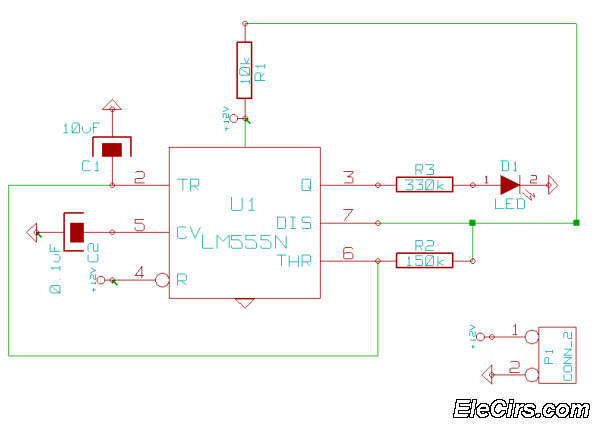
Fake Car Alarm Circuit using 555 timer
This is a very simple 555 timer circuit that serves as a straightforward theft deterrent, which may be just as effective. The idea is to have a flashing red LED indicate that your car is protected. This device can protect...
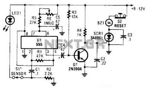
555 Based Alarm Circuit
The alarm circuit utilizes a single 555 oscillator/timer (U1) that functions in both the alarm-trigger circuit and the entry-delay circuit. In this configuration, the trigger input of U1 at pin 2 is maintained in a high state through resistor R1....
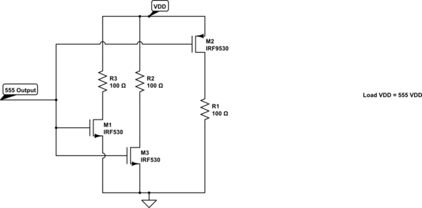
Invert a 555 Astable Output Signal
A variable frequency, variably duty cycle 555 configuration is set up in astable mode. A set of potentiometers is utilized to achieve a wide range of control. The output is functioning well; however, there is an issue. The circuit drives...
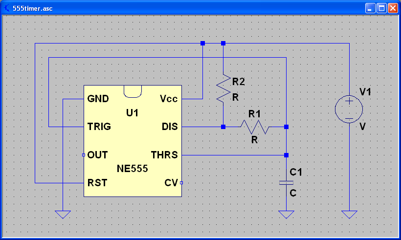
Capacitors and the 555 Timer
ECEN 2250 myDAQ Experiment Capacitors and the 555 Timer.
The experiment involving capacitors and the 555 timer within the ECEN 2250 myDAQ framework focuses on understanding the behavior of capacitors in electronic circuits and the functionality of the 555 timer as...
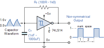
Non-standard 555 Astable Multivibrator
A square wave generator with a variable frequency and a 50% duty cycle is required. While the 555 timer is a common choice, the standard astable multivibrator configuration alters the duty cycle when the frequency is adjusted. A circuit found...
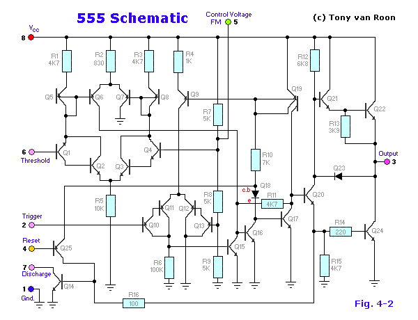
555 timer
The 555 timer IC was first introduced around 1971 by the Signetics Corporation as the SE555/NE555 and was referred to as "The IC Time Machine." It was the first commercially available timer IC, providing circuit designers and hobbyists with an...
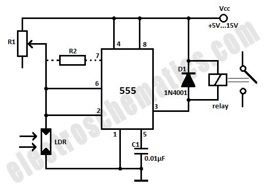
Light Activated Relay with 555 Circuit
This light-activated relay circuit utilizes the 555 timer integrated circuit (IC) and a light-dependent resistor (LDR) to create a light-sensitive relay suitable for applications such as intruder alarm systems or automatic lamp control at sunset and sunrise. The potentiometer R1...
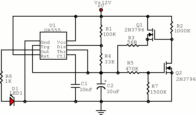
555 Pulse Generator
The first positive pulse from a classic 555-based oscillator is always 1.6 times longer than the subsequent pulses. This discrepancy arises because, during the initial cycle, capacitor C2 begins charging from 0 V. While this is typically not an issue,...
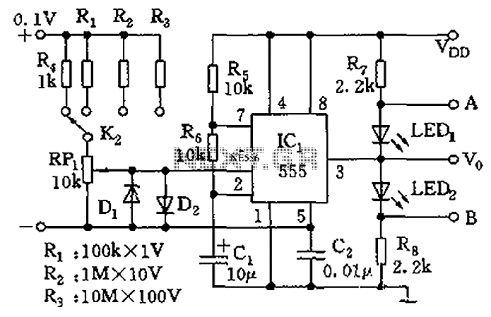
555 meter circuit diagram of a DC voltage
The control terminal at 5 feet and the threshold end at 6 feet represent two internal input voltage comparators. As long as the voltage at 6 feet exceeds the voltage at 5 feet by 5 mV, the 555 timer will...