


Single-supply-wien-bridge-oscillator
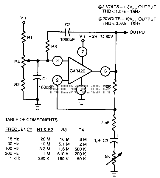
Description: The adjustment of R4 contributes to the comparatively symmetrical output transfer characteristic of the CA3420 BiMOS operational amplifier. To extend the lower operating frequency, remove C3 and use a dual supply.
The CA3420 is a high-performance BiMOS operational amplifier that combines the advantages of both bipolar and CMOS technologies. The adjustment of resistor R4 is crucial in achieving a balanced output transfer characteristic, which is essential for maintaining linearity and minimizing distortion across the output range. By fine-tuning R4, the user can optimize the amplifier's response, ensuring that it performs effectively in various applications.
To enhance the operational frequency range of the CA3420, particularly at lower frequencies, it is recommended to remove capacitor C3 from the circuit. Capacitor C3 typically serves to filter high-frequency noise or stabilize the amplifier's response; however, its presence can limit the lower frequency response. By eliminating this capacitor, the bandwidth of the amplifier can be extended, allowing it to operate effectively at lower frequencies.
Additionally, employing a dual supply configuration is advised when working with the CA3420. A dual supply provides both positive and negative voltage rails, which is beneficial for amplifying AC signals that swing above and below ground. This configuration allows for a more symmetrical output swing, further enhancing the amplifier's performance and making it suitable for a wider range of signal processing applications.
In summary, careful adjustment of R4, removal of C3, and the use of a dual supply are critical considerations for optimizing the performance of the CA3420 BiMOS operational amplifier. These modifications contribute to achieving a symmetrical output transfer characteristic and extending the operational frequency range, thereby improving the overall functionality of the circuit.The Adjustment of R4 contributes to the comparatively symmetrical output transfer characteristic of the CA3420 BiMOS op amp. To extend the lower operating frequency, remove C3 and use a dual supply.
The CA3420 is a high-performance BiMOS operational amplifier that combines the advantages of both bipolar and CMOS technologies. The adjustment of resistor R4 is crucial in achieving a balanced output transfer characteristic, which is essential for maintaining linearity and minimizing distortion across the output range. By fine-tuning R4, the user can optimize the amplifier's response, ensuring that it performs effectively in various applications.
To enhance the operational frequency range of the CA3420, particularly at lower frequencies, it is recommended to remove capacitor C3 from the circuit. Capacitor C3 typically serves to filter high-frequency noise or stabilize the amplifier's response; however, its presence can limit the lower frequency response. By eliminating this capacitor, the bandwidth of the amplifier can be extended, allowing it to operate effectively at lower frequencies.
Additionally, employing a dual supply configuration is advised when working with the CA3420. A dual supply provides both positive and negative voltage rails, which is beneficial for amplifying AC signals that swing above and below ground. This configuration allows for a more symmetrical output swing, further enhancing the amplifier's performance and making it suitable for a wider range of signal processing applications.
In summary, careful adjustment of R4, removal of C3, and the use of a dual supply are critical considerations for optimizing the performance of the CA3420 BiMOS operational amplifier. These modifications contribute to achieving a symmetrical output transfer characteristic and extending the operational frequency range, thereby improving the overall functionality of the circuit.The Adjustment of R4 contributes to the comparatively symmetrical output transfer characteristic of the CA3420 BiMOS op amp. To extend the lower operating frequency, remove C3 and use a dual supply.

Input Impedance Booster II
The input resistance of AC-coupled operational amplifier circuits is primarily determined by the resistance used for DC biasing. When using CMOS operational amplifiers, the input resistance is typically high, reaching up to 10 MΩ. For applications requiring even higher input...

Wien bridge oscillator
In the circuit, the frequency trimming component is configured such that the voltage across it is in quadrature with the voltage V0 from the bridge. This arrangement allows for adjustments to be made with minimal changes to the attenuation of...
Safety flare
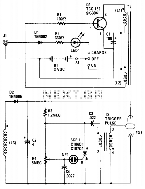
When the switch SI is activated, power is supplied to an oscillator that consists of Q1, R1, C1, L1, and L2. Coil L1 serves as the primary winding of transformer T1, while L2 functions as the feedback winding. As Q1...
Voltage comparator circuit
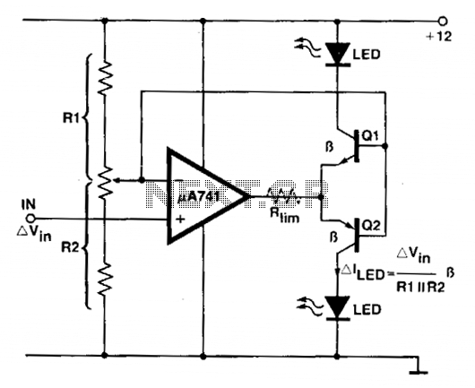
An operational amplifier (op amp) is utilized as a comparator and as a current sink for an LED. The output voltage of the amplifier varies by approximately 1.4 V based on the direction of the current. At any given moment,...
Trap MC33171
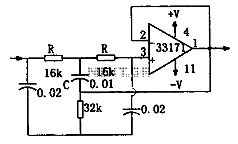
A chopper circuit is illustrated in the figure. The circuit utilizes a high-performance operational amplifier, MC33171, to create a trap. This device features a wide bandwidth and a high conversion rate. The component values can be modified by adjusting the...
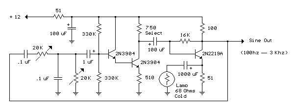
Wien Bridge RC Sinewave Oscillator
Three examples of Wien Bridge oscillators are shown below. The first uses three bipolar transistors. The second uses a bipolar and JFET, and the third is the more popular type using an op-amp for minimal parts. The idea is to...

Electronic Drum Synthesizer
The circuit consists of two twin-T oscillators set below the oscillation threshold. To initiate oscillation, a touch on the Touch Pad is required. The schematic diagram illustrates the circuit, where different touch patterns on the pads can create a variety...

Local Oscillator For Double Balanced Mixers Circuit
This circuit includes an amplifier designed to deliver +10 dBm to an SBL series (Mini-Circuits) or a similar type of doubly-balanced mixer assembly. The circuit parameters are specified for 80 to 90 MHz crystals, although the values of the oscillator...
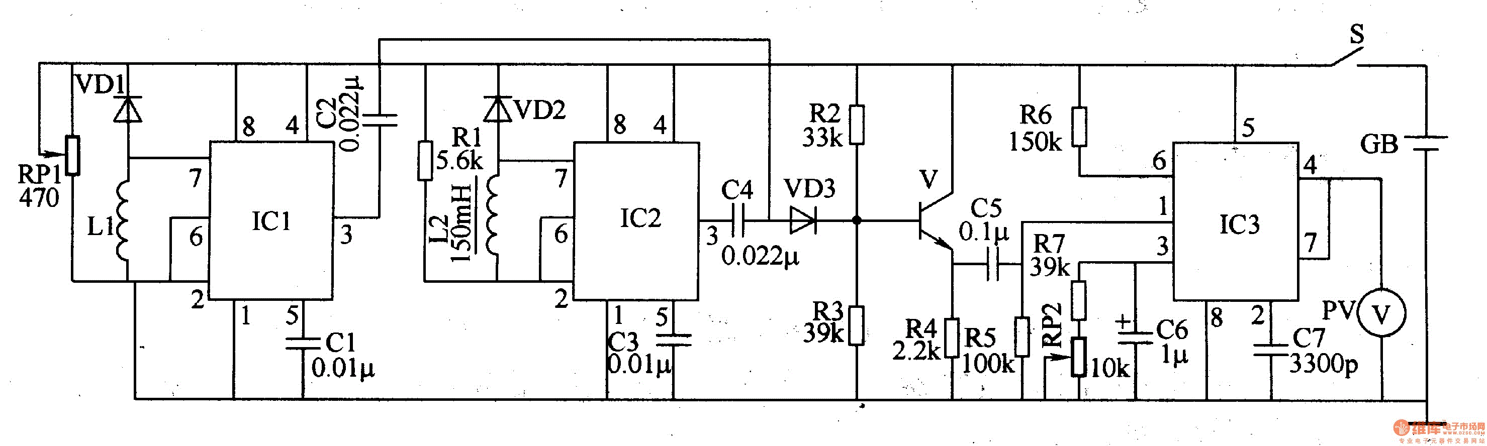
Metal detector 4
The metal detector circuit comprises a detection oscillator, a reference oscillator, a mixer, and a signal display, as illustrated in Figure 8-70. The detection oscillator circuit is made up of the time base oscillator IC1, inductor L1, potentiometer RP1, diode...