


synchronized sawtooth
#sawtooth
#synchronization
#triac
#power line frequency
#flexible voltage
#signal generation
#control circuit
#special applications
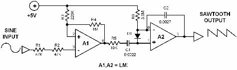
Description: The sawtooth signal generated by this simple circuit is synchronized with the power line frequency. It is originally designed to control triac circuits but can be used for other special applications. The supply voltage is highly flexible and can be any level between 4 volts and 36 volts. The values of R1 and R2 are highly dependent on the maximum input voltage. The best way to obtain the input signal is to connect the input to the power line through indirect means, such as using a step-down transformer or a high-voltage capacitor. The first operational amplifier (op-amp) A1 converts the power line sine wave signal into a square wave signal. This square wave is then fed to the second op-amp, which converts it to a sawtooth waveform. The op-amp A2 functions as a conventional integrator. Its output decreases linearly since a constant current flows through R6 to its non-inverting input. This integrator is reset to its initial state periodically with the help of the input signal. The internal design of the op-amp allows the integrator to respond to both positive and negative input signals.
The circuit operates by utilizing the characteristics of operational amplifiers to generate a sawtooth waveform from the AC power line frequency. The synchronization with the power line frequency allows for consistent timing, which is crucial for applications such as phase control in triac circuits.
The first stage of the circuit involves an operational amplifier configured as a comparator. This op-amp (A1) takes the AC sine wave from the power line, which is typically around 50 or 60 Hz, and converts it into a square wave. The output of this stage switches between high and low states, effectively creating a digital representation of the input AC signal.
The square wave output is then fed into a second operational amplifier (A2), which is configured as an integrator. The integrator takes the square wave input and produces a sawtooth output. This is achieved by integrating the square wave over time, resulting in a linear ramp-up during the high state and a rapid reset during the low state. The integration process is influenced by the resistor R6, which sets the rate of change of the output voltage. The output of the integrator decreases linearly at a rate determined by the constant current flowing through R6.
To ensure that the integrator resets to its initial state, the circuit employs a feedback mechanism that utilizes the input square wave. When the square wave transitions from high to low, it triggers the integrator to reset, allowing for continuous generation of the sawtooth waveform. The design accommodates a wide range of supply voltages, enhancing its versatility in various applications.
The component values for R1 and R2 must be selected based on the maximum input voltage to ensure proper operation and stability of the circuit. The use of a step-down transformer or high-voltage capacitor is essential to safely interface the circuit with the high voltage AC power line, preventing damage to the circuit components and ensuring safe operation. Overall, this circuit provides a reliable method for generating sawtooth signals synchronized with the power line frequency, suitable for various electronic applications.The sawtooth signal generated by this simple circuit is synchronized with the power line frequency. It is originally designed to control triac circuits but it can be used for other special applications. The supply voltage is highly flexible and can be any level between 4 volt and 36 volts. The values of R1 and R2 are highly dependent on the maximu m input voltage. The best way to obtain the input signal is to connect the input to the power line through indirect means like using an stepdown transformer or a high voltage capacitor. The first opamp A1 converts the power line sinewave signal into a squarewave signal. This squarewave is further fed to the second opamp which converts it to a sawtooth formed signal. The opamp A2 functions as a conventional integrator. Its output sinks linearly since a constant current flows through R6 to its non-inverting input. This integrator is reset to its initial state periodically with the help of the input signal. The internal design of the opamp makes the integrator react to both positive and negative input signal.
The circuit operates by utilizing the characteristics of operational amplifiers to generate a sawtooth waveform from the AC power line frequency. The synchronization with the power line frequency allows for consistent timing, which is crucial for applications such as phase control in triac circuits.
The first stage of the circuit involves an operational amplifier configured as a comparator. This op-amp (A1) takes the AC sine wave from the power line, which is typically around 50 or 60 Hz, and converts it into a square wave. The output of this stage switches between high and low states, effectively creating a digital representation of the input AC signal.
The square wave output is then fed into a second operational amplifier (A2), which is configured as an integrator. The integrator takes the square wave input and produces a sawtooth output. This is achieved by integrating the square wave over time, resulting in a linear ramp-up during the high state and a rapid reset during the low state. The integration process is influenced by the resistor R6, which sets the rate of change of the output voltage. The output of the integrator decreases linearly at a rate determined by the constant current flowing through R6.
To ensure that the integrator resets to its initial state, the circuit employs a feedback mechanism that utilizes the input square wave. When the square wave transitions from high to low, it triggers the integrator to reset, allowing for continuous generation of the sawtooth waveform. The design accommodates a wide range of supply voltages, enhancing its versatility in various applications.
The component values for R1 and R2 must be selected based on the maximum input voltage to ensure proper operation and stability of the circuit. The use of a step-down transformer or high-voltage capacitor is essential to safely interface the circuit with the high voltage AC power line, preventing damage to the circuit components and ensuring safe operation. Overall, this circuit provides a reliable method for generating sawtooth signals synchronized with the power line frequency, suitable for various electronic applications.The sawtooth signal generated by this simple circuit is synchronized with the power line frequency. It is originally designed to control triac circuits but it can be used for other special applications. The supply voltage is highly flexible and can be any level between 4 volt and 36 volts. The values of R1 and R2 are highly dependent on the maximu m input voltage. The best way to obtain the input signal is to connect the input to the power line through indirect means like using an stepdown transformer or a high voltage capacitor. The first opamp A1 converts the power line sinewave signal into a squarewave signal. This squarewave is further fed to the second opamp which converts it to a sawtooth formed signal. The opamp A2 functions as a conventional integrator. Its output sinks linearly since a constant current flows through R6 to its non-inverting input. This integrator is reset to its initial state periodically with the help of the input signal. The internal design of the opamp makes the integrator react to both positive and negative input signal.
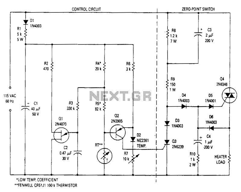
Zero-point-switching-temperature-control
This modulated triac zero-point switching circuit controls heater loads operating from 115 Vac. Circuit operation is best described by splitting the circuit into two parts. The circuit on the right is the zero-point switch; to the left is the proportional...
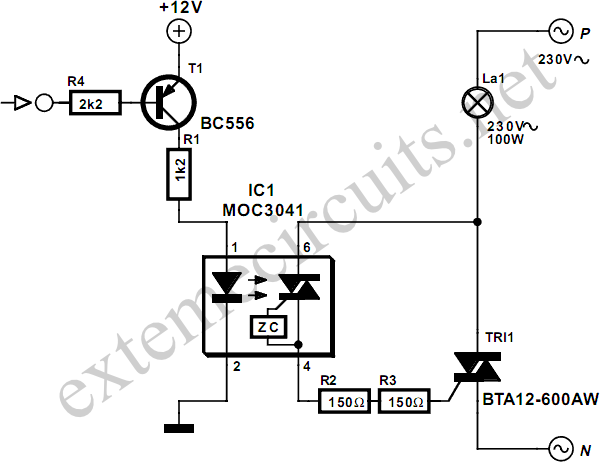
DC Control for Triacs
A relay is an effective solution for switching a mains voltage circuit, particularly in applications where long switching times and high currents are present. However, a...
A relay is an electromechanical switch that uses an electromagnetic coil to control the opening...
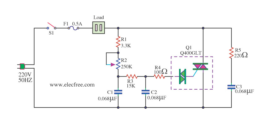
1200 Watt AC Dimmer by Triac Q4006LT
This is a 1200-watt AC power dimmer that utilizes a triac Q4006LT.
The 1200-watt AC power dimmer circuit is designed to control the brightness of incandescent lamps and other resistive loads. The core component, the triac Q4006LT, is a semiconductor device...
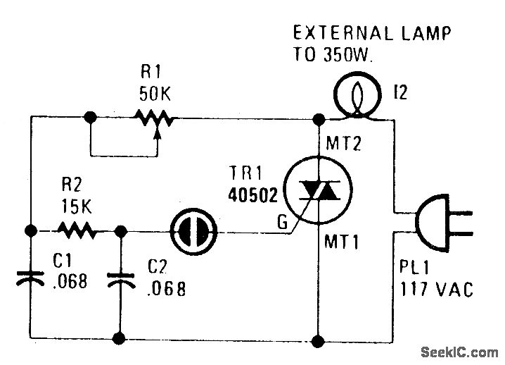
TRIAC LAMP DIMMER
A heatsink allows the TRIAC (TR1) to manage power levels up to 350 watts. The neon lamp (I1) will not activate the gate until it is in conduction, and resistor R1 is used to adjust the lighting level as desired.
The...
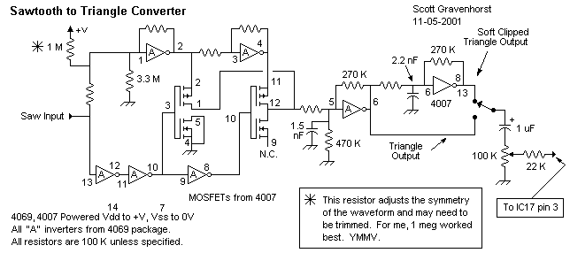
Sawtooth to triangle converter for oscillator
This wave shaper needs an input saw that goes from Vss to (ideally) Vdd. It works well with the 4069 VCO designed by Ren? Schmitz. Any saw will work as long as the wave is centered halfway between the rails....
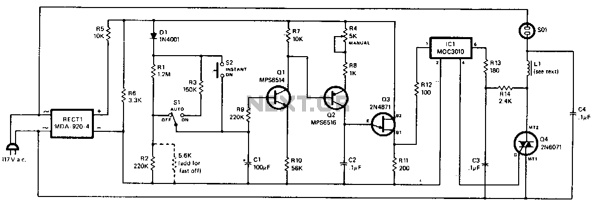
Solid-state-light-dissolver
The dimming action is controlled by varying the amount of current passed through triac Q4, which in turn regulates the lamp connected to the AC receptacle. The unijunction transistor Q3 functions as a relaxation oscillator, with its output pulse frequency...
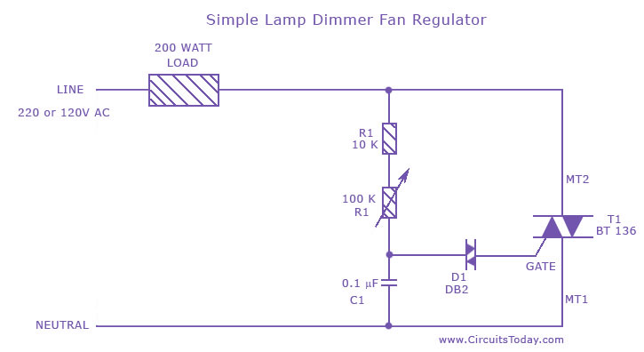
Simple Lamp Dimmer/ Fan Regulator Circuit
A fan regulator circuit that can also function as a simple lamp dimmer circuit. This fan speed regulator or light dimmer operates based on power control using a triac.
The fan regulator circuit is designed to control the speed of a...
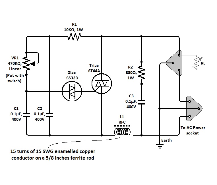
Triac Dimmer Circuit
The circuit of a simple triac light dimmer can be used to dim incandescent lamps directly from AC mains. It is easy to construct and requires very few components. A potentiometer is utilized to control the load power or light...
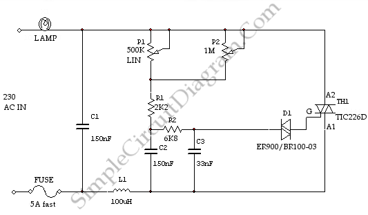
High Power AC Light Dimmer
This is a light dimmer circuit. It does not include any special features and is a typical TRIAC-based dimmer circuit. This circuit is designed to operate with...
A TRIAC-based light dimmer circuit is a common electronic design used to control the...